IA186ES/IA188ES
Data Sheet
8-Bit/16-Bit Microcontrollers
November 15, 2011
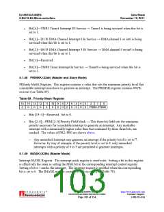
Table 67. In-Service Register (Master Mode)
15 14 13 12 11
Reserved
10
9
8
7
6
5
4
3
2
1
0
SP0 SP1 I4 I3 I2 I1 IO D1/I6 D0/I5 Res TMR
Bits [15–11]—Reserved.
Bit [10]—SP0 Serial Port 0 Interrupt Request → This is the Serial Port 0 interrupt state.
Bit [9]—SP1 Serial Port 1 Interrupt Request → This is the Serial Port 1 interrupt state.
Bits [8–4]—I [4–0] Interrupt Requests → When any of these bits is set to 1, it indicates
that the relevant interrupt has a pending interrupt.
Bit [3]—D1/I6 DMA Channel 1/Interrupt 6 Request → When set to 1, it indicates that
either the DMA channel 1 or int6 has a pending interrupt.
Bit [2]—D0/I5 DMA Channel 0/Interrupt 5 Request → When set to 1 it indicates that
either the DMA channel 0 or int5 has a pending interrupt.
Bit [1]—Reserved.
Bit [0]—TMR Timer Interrupt Request → This is the timer interrupt state and is the
logical OR of the timer interrupt requests. When set to 1, it indicates that the timer
control unit has a pending interrupt.
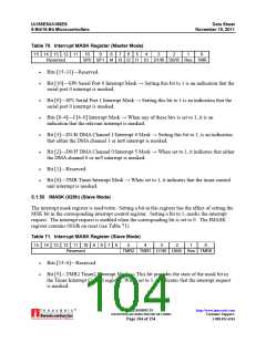
5.1.47 INSERV (02ch) (Slave Mode)
This read-only register results in the status of interrupt request bits being presented to the
interrupt controller. The status of these bits is available when this register is read. This register
is read-only.
When an internal interrupt request (D1/I6, D0/I5, TMR2, TMR1, and TMR0) occurs, the
respective bit is set to 1. The internally generated interrupt acknowledge resets these bits. The
REQST register contains 0000h on reset (see Table 68).
Table 68. In-Service Register (Slave Mode)
15 14 13 12 11 10
Reserved
9
8
7
6
5
4
3
2
1
0
TMR2 TMR1 D1/I6 D0/I5 Res TMR0
Bits [15–6]—Reserved.
Bit [5]—TMR2 Timer2 Interrupt In Service → Timer2 is being serviced when this bit is
set to 1.
®
IA211050902-19
UNCONTROLLED WHEN PRINTED OR COPIED
http://www.innovasic.com
Customer Support:
Page 102 of 154
1-888-824-4184

 INNOVASIC [ INNOVASIC, INC ]