XMC4500
XMC4000 Family
Electrical Parameters
3.3.9.5 SDMMC Interface Timing
Note: These parameters are not subject to production test, but verified by design and/or
characterization.
Note: Operating Conditions apply, total external capacitive load CL = 40 pF.
AC Timing Specifications (Full-Speed Mode)
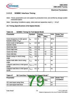
Table 46
SDMMC Timing for Full-Speed Mode
Parameter
Symbol
Values
Min.
Unit Note/ Test
Condition
Max.
Clock frequency in full speed
transfer mode (1/tpp)
fpp
tpp
CC 0
24
MHz
ns
Clock cycle in full speed
transfer mode
CC 40
−
Clock low time
Clock high time
Clock rise time
Clock fall time
tWL
CC 10
CC 10
CC −
CC −
−
ns
ns
ns
ns
ns
tWH
tTLH
tTHL
−
10
10
−
Inputs setup to clock rising
edge
tISU_F SR 2
Inputs hold after clock rising
edge
tIH_F SR 2
−
ns
ns
ns
Outputs valid time in full speed tODLY_F CC −
mode
10
−
Outputs hold time in full speed tOH_F CC 0
mode
Table 47
SD Card Bus Timing for Full-Speed Mode1)
Parameter
Symbol
Values
Unit Note/ Test
Condition
Min.
Max.
SD card input setup time
SD card input hold time
tISU
tIH
5
5
−
−
ns
ns
Data Sheet
79
V1.0, 2013-01
Subject to Agreement on the Use of Product Information

 INFINEON [ Infineon ]