XMC4500
XMC4000 Family
Electrical Parameters
t1
t2
t4
70%
30%
SDA
SCL
t1
t3
t2
t6
9th
clock
t7
t5
t10
S
SDA
SCL
t8
t7
t9
9th
clock
Sr
P
S
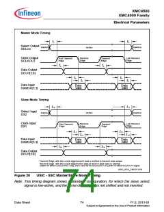
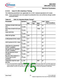
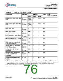
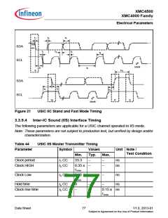
Figure 21
USIC IIC Stand and Fast Mode Timing
3.3.9.4 Inter-IC Sound (IIS) Interface Timing
The following parameters are applicable for a USIC channel operated in IIS mode.
Note: These parameters are not subject to production test, but verified by design and/or
characterization.
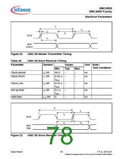
Table 44
USIC IIS Master Transmitter Timing
Parameter
Symbol
Values
Unit Note /
Test Condition
Min.
Typ.
Max.
Clock period
Clock HIGH
t1 CC
t2 CC
33.3
−
−
−
−
ns
ns
0.35 x
t1min
Clock Low
t3 CC
0.35 x
t1min
−
−
−
ns
Hold time
t4 CC
t5 CC
0
−
−
ns
Clock rise time
−
0.15 x ns
t1min
Data Sheet
77
V1.0, 2013-01
Subject to Agreement on the Use of Product Information

 INFINEON [ Infineon ]