Forced Quasi Resonant ZVS flyback controller
Configuration
5
Configuration
This chapter contains an overview about the parameters and functions that can be configured via the UART interface at GPIO
pin. Furthermore the configuration procedure is described. Mapping overviews show the correlation between the data sheet
parameters and the correlated firmware symbols. Furthermore the equations are listed to provide the specific correlation
between the configured FW parameter and the system parameter.
The chapter “configuration” is grouped in following sections:
•
•
Overview of configuration parameters using .dp Vision (Chapter 5.1)
Overview of configurable parameters and functions (Chapter 5.2)
The following shown default parameter settings correlate to the firmware version REV 1.0 .
5.1
Overview of configurable parameters using .dp Vision
The Infineon graphic user interface (GUI) .dp Vision connects to XDPS21081 via the isolated USB interface board called .dp
Interface Gen2. The .dp interface Gen2 provides power via VCC to XDPS21081 and connects via UART interface at pin
GPIO/UART. The common UART interface enables communication with the IC even without the interactive GUI tool. This
allows easy configuration during mass production.
For project development, a graphic user interface called .dp Vision guides the designer through the configuration of
parameters. More detailed information on .dp Vision can be found in the .dp Vision User Manual prepared by Infineon.
5.2
Overview of configurable parameters and functions
There are 2 types of parameters; configurable and fixed. The configurable parameters are allowed to change. On the other
hands, the fixed parameters are not recommended to change. The list of parameters shown is default value and has been
verified in the 65W HD adapter demonstrator. The parameters are typical values. Please refer to the corresponding electrical
characteristics in Chapter 6.5 for the min/max tolerances.
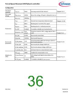
5.2.1
Configurable parameters and functions
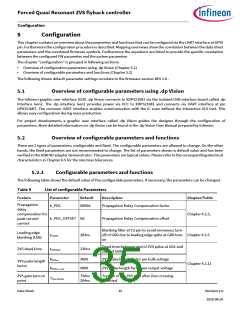
The following table shows the default value of the configurable parameters. If necessary, the parameters can be changed.
Table 8
List of configurable Parameters
Feature
Parameter
Default
Description
Chapter/Table
Propagation
delay
k_PDC
9000d
Propagation Delay Compensation factor
compensation for
peak current
control
Chapter 4.2.3,
k_PDC_OFFSET 0d
Propagation Delay Compensation offset
Blanking filter at CS pin to avoid erroneous turn-
off of GD0 due to leading edge spike at GD0 turn- Chapter 4.2.5
on
Leading edge
blanking (LEB)
283ns
tCSLEB
Dead-time between end of ZVS pulse at GD1 and
start of GD0
ZVS dead-time
236ns
tZVSdead
3600
9000
ZVS pulse length factor per bulk voltage
Chapter 4.2.11
ZVS pulse length factor per output voltage
kZVSon
ZVS pulse length
factor
kZVSon_vout
ZVS gate turn on
point
750ns
204ns
Turn on of the ZVS gate after Zero crossing
detected
Tzvs_turnon
Data Sheet
35
Revision 2.0
2020-08-20

 INFINEON [ Infineon ]