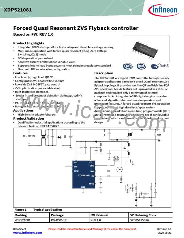
Forced Quasi Resonant ZVS flyback controller
Functional Description
exceeded for longer than tCSOCP2BL = 616.2 ns during normal operation or tCSOCP2BL = 1.001 µs during startup operation, auto-
restart mode (see Chapter 4.3.1) is entered. In this way, over-heating of the flyback converter is avoided.
4.3.8
Vcc Over-Voltage Protection (VccOVP)
The implemented VCC Over-Voltage protection prevent IC from damage caused by unregulated Vcc which may exceed max
allowed Vcc level. Once Vcc exceed 21.8V (typ.) and last for longer than blanking time 100µs , IC stop switching immediately
and trigger auto restart mode.
The normal operation will be resumed as soon as VccOVP is removed.
4.3.9
MFIO pin high (MFIOH)
There are several phenomena that causes MFIO pin high; feedback loop open, overload, etc. The feedback open-loop
protection is implemented by means of a digital comparator C2 (see Figure 3). When the voltage at MFIO pin exceeds the
threshold VMFIOH = 2.41 V, a timer is triggered. Auto-restart mode (see Chapter 4.3.1) is entered if the timer exceeds the period
of tMFIOH = 31.3 ms. This is mainly for open loop and startup protection, during startup, since the output voltage hasn’t reach
the setpoint, MFIO pin voltage is always high.
4.3.10
Internal over-temperature detection (IntOTP)
An internal over-temperature protection is implemented in this control IC. Once the internal temperature exceeds the
threshold of TJOTP = 130 °C for longer than the blanking time tJOTP = 10.5 ms, internal over-temperature is detected and the
control IC enters auto-restart mode (see Chapter 4.3.1). The normal operation will be resumed if the internal temperature is
dropped by 20 °C from TJOTP
.
4.3.11
Primary side output Over-Voltage Protection (VoutOVP)
The IC provides primary side output over-voltage detection via the ZCD pin. Here the reflected output voltage from the
flyback transformer is sampled at ZCD pin during the demagnetization phase (see Chapter 4.2.1.1). In each switching cycle,
the XDPS21081 compares the measured output voltage VZCDVO with the output over-voltage threshold VZCDOVP = 2.75V.
That comparison can refer to
•
•
The demagnetization phase of the same switching cycle or
The demagnetization phase of an earlier switching cycle.
A blanking filter is implemented to avoid erroneous output over-voltage detection. This filter consists of a symmetrical
counter. Each comparison where VZCDVO < VZCDOVP, will decrement the counter (but not below zero) while each comparison
where VZCDVO ≥ VZCDOVP will increment the counter. If the counter is increased to NZCDOVP+1, auto-restart mode (see Chapter 4.3.1)
is entered. This protection mode is a configurable parameter. It can be changed to latch mode (see Chapter 4.3.2) by .dp
Vision.
4.3.12
Over load power protection
The IC provides protection against over load by means of the integrated maximum peak current limitation combined with
an over-load timer (OLPT). Once OLP is detected, the control IC enters auto-restart mode (see Chapter 4.3.1).
XDPS21081 uses current mode control, so the OCP1 Look-Up-Table (LUT) values are designed by considering the propagation
delay at different line voltages and operation modes. Once the OCP1 LUT value is hit, the OLP timer will start to count up. The
counter will reduce the count if OCP1 LUT value is not hit in the cause of OCP1 protection. Finally the IC will enter AR if
protection timer reaches the pre-definite time.
This protection can distinguish with open loop protection by setting different OLP timer. E.g during power up, Vmfio is always
high before voltage rise up, so with different timer, it can separately control the open loop protection and over load
protection.
Data Sheet
33
Revision 2.0
2020-08-20

 INFINEON [ Infineon ]