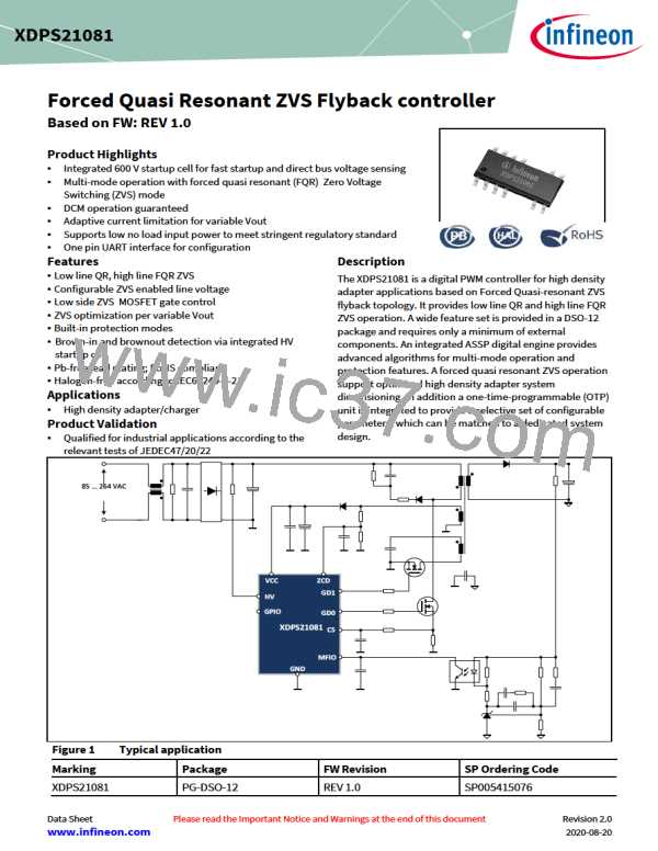
Forced Quasi Resonant ZVS flyback controller
Functional Description
4.3.2
Latch Mode (LM)
When latch mode is entered, the gate driver switching at GD0 pin is stopped and the control IC enters stand-by mode where
the current consumption is reduced to IVCCquLM = 150 µA. During the latch mode the HV startup-cell is operating in the bang-
bang mode to keep the IC alive and staying in latch mode. Here the voltage VVCC is varying in a wider range compared to the
bang-bang mode operation in auto-restart mode (see Chapter 4.1.5.1).
4.3.3
VCC Under-Voltage lockout (UVOFF)
The implemented VCC under-voltage lockout (UVLO) ensures a defined activation and deactivation of the IC operation
depending on the supply voltage VVCC. The UVLO contains a hysteresis with the voltage thresholds VVCCon = 20.5 V for
activating the IC. For deactivating the IC, two thresholds are defined. They are:
•
•
V
V
VCCoff = 7.2 V during normal operation / during auto-restart break time
VCCoffBO = 9.6 V after brown-out detected
The higher VVCCoffBO threshold leads to earlier deactivation of the IC and earlier charge-up of the VCC capacitor and supports
a new system startup earlier.
Both VCC on- and off-thresholds contain a spike blanking tVCCon and tVCCoff
.
4.3.4
Brown-In Protection (BIP)
At initial power-up or auto-restart, the brown-in condition at the HV pin and at the VCC pin must be fulfilled for starting the
soft-start procedure. The controller measures the current at HV pin through the internal shunt resistor RM (see Figure 3). The
input brown-in is fulfilled if the current IHV exceeds the threshold IHVBI = 1.15 mA. The VCC brown-in is fulfilled if the voltage
V
VCC is above the threshold VVCCBI = 15 V. No blanking time applies for brown-in detection. If one of the brown-in conditions is
not fulfilled, the IC stays active, but without gate switching. The voltage at VCC pin drops then. Once it falls below the
threshold VVCCoff = 7.2 V, the control IC is deactivated, and the startup cell is turned on automatically to charge up the VCC
capacitor.
4.3.5
Brown-Out Protection (BOP)
The brown-out protection for bulk voltage prevents the IC from operating with a too low line voltage, which could lead to
high RMS current stress in the application. Brown-out detection is also performed via the HV pin as for brown-in detection.
Here an under-voltage detection of the bulk voltage VBulk is provided to support brown-out protection. The measured current
IHV is compared with the bulk under-voltage detection threshold IHVBO = 0.443 mA. The brown-out protection applies if bulk
under-voltage is detected for certain blanking time. This blanking time is set to tHVBO = 1.09 ms during normal operation and
to tHVBOSS = 5.27 ms during soft-start phase. Once brown-out protection is entered, the IC stops switching.
4.3.6
Over-Current Protection level 1 (OCP1)
The over-current protection level 1 (OCP1) is performed by means of the cycle-by-cycle peak current control via the
comparator OCP1 (see Figure 3). A leading edge blanking (see Chapter 4.2.5) prevents the IC from false switching-off the
power MOSFET due to the leading edge spike. The maximum peak setting for VCS is compensated by the propagation delay
compensation (see Chapter 4.2.3), to provide an input voltage level independent current limitation. The highest peak setting
for VCS of VCSmaxLL(max) = 402mV occurs at low-line and defines the maximal saturation current of the flyback transformer.
4.3.7
Over-Current Protection level 2 (OCP2)
The over-current protection level 2 (OCP2) protects the flyback converter under critical fault conditions such as shorted
transformer windings or shorted secondary side rectifier diode. In this case, the repeating cycle-by-cycle over-current
protection level OCP1 cannot properly limit the inductor current due to the very steep slope of the current ramp and the
propagation delay in the peak current control. With the over-current protection OCP2, once the threshold VCSOCP2 = 0.6V is
Data Sheet
32
Revision 2.0
2020-08-20

 INFINEON [ Infineon ]