OPTIREG™ SBC TLE9274QXV33
DC/DC regulators
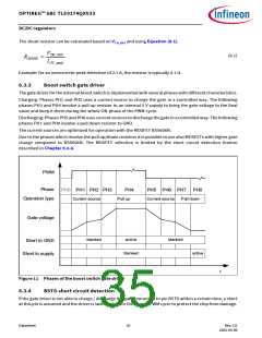
For detecting short to GND (during PWM on) or short to supply (during PWM off) the following voltage
threshold is used:
•
•
Criteria for short to GND during PH4: VBSTG < VBSTG,sc
Criteria for short to supply during PH0: VBSTG > VBSTG,sc
The short detection feature is blanked during the charging in PH1, PH2, PH3 and during discharging in phases
PH5, PH6, PH7.
When a short is detected also the bit BST_GSH in the status register SMPS_STAT is set.
6.4
Power scenarios
The chapter describes the features and performance of the buck and boost regulators according to SBC mode.
6.4.1
Buck and boost in SBC Normal mode
In SBC Normal mode, the buck regulator operates in PWM mode with fixed switching frequency. The
microcontroller and other loads on the ECU are typically supplied with a 3.3V output voltage. All supervision
functions for buck regulator are available in SBC Normal mode (for more details, refer to Chapter 13.5.1,
Chapter 13.5.2, Chapter 13.5.3 and Chapter 13.8).
6.4.2
Buck and boost in SBC Stop mode operation
The SBC Stop mode operation is intended to reduce the total amount of quiescent current while still providing
supply for microcontroller. In order to achieve this, the buck regulator automatically changes the modulation
from PWM (Pulse Width Modulation) to PFM (Pulse Frequency Modulation) when entering SBC Stop mode. In
case the boost regulator in SBC Stop mode is enabled and running, it operates only in PWM mode.
6.4.2.1 Automatic transition from PFM to PWM in SBC Stop mode
In SBC Stop mode, the buck converter operates in PFM mode by default to reduce current consumption. If
more current is needed, an automatic transition from PFM to PWM modulation is implemented. When the
buck regulator output current exceeds the IPFM-PWM,TH threshold, the buck module changes the modulation to
PWM and an INT event is generated. In addition, the PFM_PWM bit on WK_STAT_1 is set.
In order to set the buck modulation again in PFM, it is necessary to write a Stop mode command to M_S_CTRL
register. This command has to be sent when the required buck output current is below the IPFM-PWM,TH
threshold.
When entering SBC Stop mode, the automatic transition from PFM to PWM mode is activated after the time
tlag, which is the transition time where the buck regulator loop changes the modulation technique. Two
possible values can be configured via SPI command.
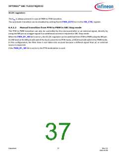
The Figure 12 shows the timing transition from SBC Normal to SBC Stop mode.
SPI Commands
Buck modulation
Normal Mode
PWM
Stop Mode
Auto PFM ↔ PWM
PWM
t
tlag
Figure 12 Transition from SBC Normal to SBC Stop mode
Datasheet
36
Rev.2.0
2022-05-06

 INFINEON [ Infineon ]