OPTIREG™ SBC TLE9274QXV33
System features
First battery connection
SBC Soft Reset
SBC Init Mode *
(Long open window)
VCC1
ON
VCC2
OFF
Boost
OFF
WD
config.
* The SBC Development Mode
is a super set of state machine
where the WD timer is stopped.
Otherwise, there are no
Any SPI
command
Cyc.Wake
OFF
FO
inact.
CAN
OFF
LINx
OFF
differences in behavior.
SBC Normal Mode
VCC1
VCC2
1) Boost
WD
WD trig
ON
OFF/ON conf./OFF config.
Cyc.Wake
config.
FO
CAN
LINx
config.
act./Inact. config.
SPI cmd
SPI cmd
SPI cmd
.
.
Reset is released
WD starts with long open window
Automatic
SBC Stop Mode
1) Boost
SBC Sleep Mode
VCC1
ON
VCC2
WD
VCC1
OFF
VCC2
OFF/ON
Boost
OFF
WD
OFF
VCC1 over voltage
(if VCC1_OV_RST set)
OFF/ON fixed/OFF fixed/OFF
4) CAN
Wake
LINx
Wake
Cyc.Wake
fixed
FO
act./Inact.
CAN
fixed
LINx
fixed
Cyc.Wake
OFF
FO
act./Inact.
cap./OFF cap./OFF
CAN, WK, LIN1..4 wake-up
event
SBC Restart Mode
(RO pin is asserted)
WD Failure
(Config 1/3)
VCC1
ON/
ramping
VCC2
OFF
2) CAN
woken/
OFF
1) Boost
fixed/OFF
2) LINx
woken/
OFF
WD
OFF
VCC1
Undervoltage
Cyc.Wake
OFF
FO
act./Inact.
SBC Fail-Safe Mode
TSD2 event
VCC1
OFF
VCC2
OFF
Boost
OFF
WD
OFF
VCC1 Short
to GND
CAN, WK, LINx wake-up event
CAN
wake
capable
LINx
wake
capable
Cyc.Wake
OFF
FO
active
1) The Boost regulator activation depends from the VS value.
2) See chapter CAN and LIN for detailed behaviour in SBC Restart Mode
3) See Chapter 5.1.5 and 12.1 for detailed FOx behavior
4) Must be set to CAN wake capable / CAN OFF mode before entering SBC sleep mode
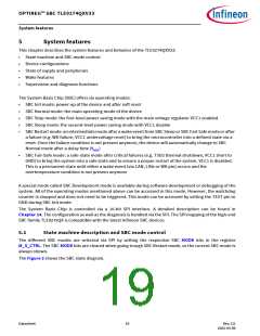
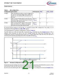
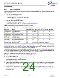
Figure 3
State diagram showing the SBC operating modes
5.1.1
SBC Init mode and device configuration
The SBC Init mode is the mode where the hardware configuration of the SBC is stored and where the
microcontroller finishes the initialization phase. During the SBC Init mode, the SBC can be configured in
normal operation or in SBC Development mode (see also Chapter 5.1.7).
The hardware configuration is done monitoring the level of FO3/TEST pin. The pin FO3/Test is set as an input
and one internal pull-up resistor is activated (RTEST). The Table 6 shows possible hardware configurations.
Datasheet
20
Rev.2.0
2022-05-06

 INFINEON [ Infineon ]