OPTIREG™ SBC TLE9274QXV33
System features
5.1.5
SBC Restart mode
There are multiple reasons to enter the SBC Restart mode. The purpose of the SBC Restart mode is to reset the
microcontroller:
•
From SBC Normal and Stop mode:
–
–
–
Undervoltage on VCC1
Overvoltage on VCC1 (if VCC1_OV_ RST is set)
Incorrect Watchdog triggering
•
From SBC Sleep and Fail-Safe mode:
–
–
Wake-up event on CAN or LINx or WK
After TDS2 (only from SBC Fail-Safe mode. See also Chapter 13.8)
Table 7 contains detailed descriptions of the reason to restart.
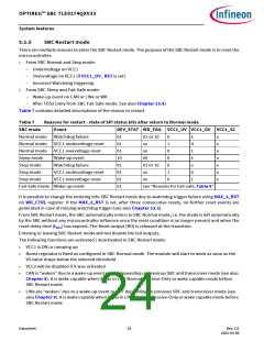
Table 7
Reasons for restart - state of SPI status bits after return to Normal mode
Event DEV_STAT WD_FAIL VCC1_UV VCC1_OV VCC1_SC
SBC mode
Normal mode Watchdog failure
01
01
01
10
01
01
01
01
01 or 10
0
1
0
0
0
1
0
x
0
1
x
x
0
1
x
x
x
x
x
x
x
Normal mode VCC1 undervoltage reset
Normal mode VCC1 overvoltage reset
xx
xx
Sleep mode
Stop mode
Stop mode
Stop mode
Wake-up event
00
Watchdog failure
01 or 10
VCC1 undervoltage reset
VCC1 overvoltage reset
xx
xx
Fail-Safe mode Wake-up event
see “Reasons for Fail-safe, Table 8”
It is possible to change the entering into SBC Restart mode due to watchdog trigger failure using MAX_3_RST
on WD_CTRL register. If the MAX_3_RST is set, after three consecutive resets, no further reset events are
generated in case of missing watchdog trigger (see also Chapter 13.2).
From SBC Restart mode, the SBC automatically enters to SBC Normal mode, i.e. the mode is left automatically
by the SBC without any microcontroller influence once the reset condition is no longer present and when the
reset delay time (tRD1) has expired. The Reset output (RO) is released at the transition.
Entering or leaving SBC Restart mode will not disable the fail outputs.
The following functions are activated / deactivated in SBC Restart mode:
•
•
VCC1 is ON or ramping up
Boost regulator is fixed as configured in SBC Normal mode. The module will start to work as soon as the
VS value drops below the selected threshold
•
•
VCC2 will be disabled if it was activated
CAN is “woken” due to a wake-up event or OFF depending on previous SBC and transceiver mode (see also
Chapter 8). It is wake capable when it was in CAN Normal, Receive-Only or wake capable mode before
SBC Restart mode
•
LINx are “woken” due to a wake-up event or OFF depending on previous SBC and transceiver mode (see
also Chapter 9). It is wake capable when it was in LINx Normal, Receive-Only or wake capable mode before
SBC Restart mode
Datasheet
24
Rev.2.0
2022-05-06

 INFINEON [ Infineon ]