OPTIREG™ SBC TLE9274QXV33
System features
5
System features
This chapter describes the system features and behavior of the TLE9274QXV33:
•
•
•
•
•
State machine and SBC mode control
Device configurations
State of supply and peripherals
Wake features
Supervision and diagnosis functions
The System Basis Chip (SBC) offers six operating modes:
•
•
•
•
•
SBC Init mode: power-up of the device and after soft reset
SBC Normal mode: the main operating mode of the device
SBC Stop mode: the first-level power saving mode with the main voltage regulator VCC1 enabled
SBC Sleep mode: the second-level power saving mode with VCC1 disable
SBC Restart mode: an intermediate mode after a wake event from SBC Sleep or SBC Fail-Safe mode or after
a failure (e.g. WD failure, VCC1 undervoltage reset) to bring the microcontroller into a defined state via a
reset. Once the failure condition is not present anymore, the device will automatically change to SBC
Normal mode after a delay time (tRD1
)
•
SBC Fail-Safe mode: a safe-state mode after critical failures (e.g. TSD2 thermal shutdown, VCC1 short to
GND) to bring the system into a safe state and to ensure a proper restart of the system. VCC1 is disabled.
This is a permanent state until either a wake event (via CAN, LINx or WK pin) occurs and the
overtemperature condition is not present anymore
A special mode called SBC Development mode is available during software development or debugging of the
system. All of the operating modes mentioned above can be accessed in this mode. However, the watchdog
counter is stopped and does not need to be triggered. This mode can be accessed by setting the TEST pin to
GND during SBC Init mode.
The System Basis Chip is controlled via a 16-bit SPI interface. A detailed description can be found in
Chapter 14. The configuration as well as the diagnosis is handled via the SPI. The SPI mapping of the high-end
SBC family TLE927xQX is compatible with the latest Infineon SBC devices.
5.1
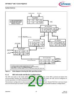
State machine description and SBC mode control
The different SBC modes are selected via SPI by setting the respective SBC MODE bits in the register
M_S_CTRL. The SBC MODE bits are cleared when going trough SBC Restart mode, so the current SBC mode is
always shown.
The Figure 3 shows the SBC state diagram.
Datasheet
19
Rev.2.0
2022-05-06

 INFINEON [ Infineon ]