OPTIREG™ SBC TLE9274QXV33
Application information
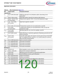
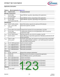
Table 25 Bill of material for Figure 15.2 (cont’d)
Ref.
Typical value
Purpose/comment
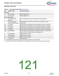
Active Components
D1
e.g. SS34HE3/9AT
Reverse polarity protection. Depending for the application
(Vishay)
DLIN1
DLIN2
DLIN3
DLIN4
T1
e.g. BAS70
e.g. BAS70
e.g. BAS70
e.g. BAS70
e.g. BCR191W
e.g. BCR191W
e.g. BCR191W
e.g. XC2xxx
Requested by LIN standard; reverse polarity protection of network
Requested by LIN standard; reverse polarity protection of network
Requested by LIN standard; reverse polarity protection of network
Requested by LIN standard; reverse polarity protection of network
High active FO1 control
T2
High active FO2 control
T3
High active FO3 control
µC
Microcontroller
1) The input EMI filter has to be evaluated in according with the final application. The values are only given as hint.
2) The saturation current has to be define in according with the maximum current required by the application.
3) For optimum dynamic behavior, C4 and C5 = 22 µF ±20%, 16 V ceramic low ESR.
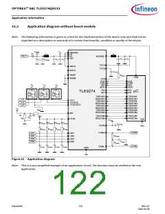
5V_int
SBC Init
Mode
Ttest
RTEST
Connector/
FO3/
Jumper
TEST
REXT
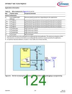
TFO_PL
Failure Logic
Figure 53 Hint for increasing the robustness of pin FO3/TEST during debugging or programming
Datasheet
124
Rev.2.0
2022-05-06

 INFINEON [ Infineon ]