OPTIREG™ SBC TLE9274QXV33
Application information
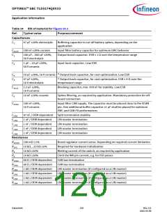
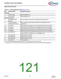
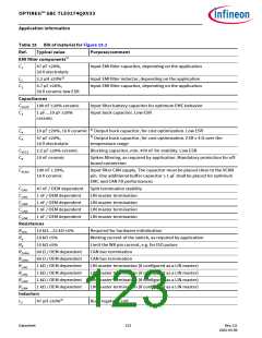
Table 24 Bill of material for Figure 15.1 (cont’d)
Ref.
Typical value
Purpose/comment
Inductors
L1
L2
22 µH ±20%2)
47 µH ±20%2)
Boost regulator coil
Buck regulator coil
Active components
D1
e.g. SS34HE3/9AT
Reverse polarity protection. Depending for the application
(Vishay)
D2
e.g. SL04-GS08 or
SS34HE3/9AT (Vishay)
Boost regulator power diode. Forward current depends on the
application
DLIN1
DLIN2
DLIN3
DLIN4
e.g. BAS70
e.g. BAS70
e.g. BAS70
e.g. BAS70
Requested by LIN standard; reverse polarity protection of network
Requested by LIN standard; reverse polarity protection of network
Requested by LIN standard; reverse polarity protection of network
Requested by LIN standard; reverse polarity protection of network
TBOOST e.g. BSS606N
Boost regulator external MOSFET. Maximum Rds_on ≤ 100 mΩ, Drain
current max ≤ 3 A, Drain-Source max voltage ≤ 60 V
T1
T2
T3
µC
e.g. BCR191W
e.g. BCR191W
e.g. BCR191W
e.g. XC2xxx
High active FO1 control
High active FO2 control
High active FO3 control
Microcontroller
1) For for optimum dynamic behavior, C4 and C5 = 22 µF ±20%, 16 V ceramic low ESR.
2) The saturation current has to be define in according with the maximum current required by the application.
Datasheet
121
Rev.2.0
2022-05-06

 INFINEON [ Infineon ]