OPTIREG™ SBC TLE9274QXV33
Application information
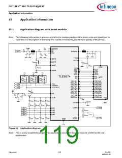
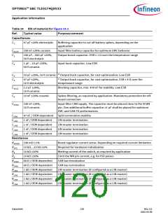
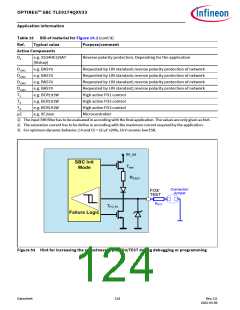
Table 24 Bill of material for Figure 15.1
Ref.
Typical value
Purpose/comment
Capacitances
C1
47 µF ±20% electrolytic Buffering capacitor to cut off battery spikes, depending on the
application
CVSUP
C2
100 nF ±20% ceramic
Input filter battery capacitor for optimum EMC behavior
100 µF…560 µF ±20%,
50 V electrolytic
Output boost capacitor. ESR ≤ 1 Ω over the temperature range
C3
1 µF…10 µF ±20%,
50 V ceramic
Input buck capacitor. Low ESR
C4
C5
10 µF ±20%, 16 V ceramic 1) Output buck capacitor, for cost optimization. Low ESR
47 µF ±20%,
1) Output buck capacitor, for cost optimization. ESR ≤ 4 Ω over the
16 V electrolytic
temperature range
CVCC2
C9
2.2 µF ±20%,
16 V ceramic
Blocking capacitor, min. 470 nF for stability. Low ESR
10 nF ±20% ceramic
Spikes filtering, as required by application. Mandatory protection for off-
board connection
CVCAN
100 nF ±20%,
16 V ceramic
Input filter CAN supply. The capacitor must be placed close to the VCAN
pin. One additional buffer capacitor ≥1 µF shall be placed for optimum
EMC and CAN FD performances
CCAN
CLIN1
CLIN2
CLIN3
CLIN4
47 nF / OEM dependent Split termination stability
1 nF / OEM dependent
1 nF / OEM dependent
1 nF / OEM dependent
1 nF / OEM dependent
LIN master termination
LIN master termination
LIN master termination
LIN master termination
Resistances
RSENSE 100 mΩ ±1%
Boost regulator current sense. Depending on required current limitation
Required for hardware initialization
RCFG
R4
10 kΩ…22 kΩ ±5%
10 kΩ ±20%
Wetting current of the switch, as required by application
Limit the WK pin current, e.g. for ISO pulses
CAN bus termination
R5
10 kΩ ±20%
RCANH
RCANL
RLIN1
RLIN2
RLIN3
RLIN4
60 Ω / OEM dependent
60 Ω / OEM dependent
1 kΩ / OEM dependent
1 kΩ / OEM dependent
1 kΩ / OEM dependent
1 kΩ / OEM dependent
CAN bus termination
LIN master termination (if configured as a LIN master)
LIN master termination (if configured as a LIN master)
LIN master termination (if configured as a LIN master)
LIN master termination (if configured as a LIN master)
Datasheet
120
Rev.2.0
2022-05-06

 INFINEON [ Infineon ]