TC1767
Electrical Parameters
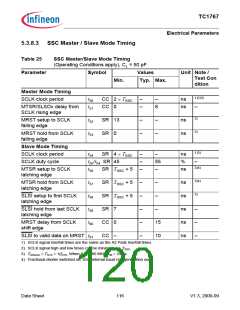
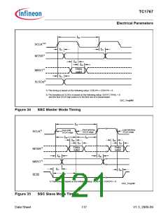
5.3.8.3 SSC Master / Slave Mode Timing
Table 25
SSC Master/Slave Mode Timing
(Operating Conditions apply), CL = 50 pF
Parameter
Symbol
Values
Typ. Max.
Unit Note /
Test Con
dition
Min.
Master Mode Timing
1)2)3)
SCLK clock period
t50
t51
CC 2 × TSSC
–
–
–
8
ns
MTSR/SLSOx delay from
SCLK rising edge
CC 0
ns
ns
ns
–
3)
MRST setup to SCLK
falling edge
t52
t53
SR 13
SR 0
–
–
–
–
3)
MRST hold from SCLK
falling edge
Slave Mode Timing
SCLK clock period
SCLK duty cycle
1)3)
t54
SR 4 × TSSC
–
–
–
–
ns
%
t55/t54 SR 45
55
–
–
3)4)
MTSR setup to SCLK
latching edge
t56
t57
t58
t59
t60
SR TSSC + 5
ns
3)4)
3)
MTSR hold from SCLK
latching edge
SR TSSC + 5
SR TSSC + 5
SR 7
–
–
–
–
–
–
ns
ns
ns
ns
ns
SLSI setup to first SCLK
latching edge
–
SLSI hold from last SCLK
latching edge
–
–
–
–
MRST delay from SCLK
shift edge
CC 0
15
10
SLSI to valid data on MRST t61
CC –
1) SCLK signal rise/fall times are the same as the A2 Pads rise/fall times.
2) SCLK signal high and low times can be minimum 1 × TSSC
3) TSSCmin = TSYS = 1/fSYS. When fSYS = 80 MHz, t50 = 25 ns.
.
4) Fractional divider switched off, SSC internal baud rate generation used.
Data Sheet
116
V1.3, 2009-09

 INFINEON [ Infineon ]