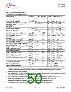
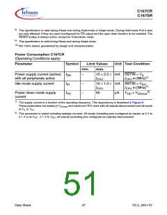
C167CR
C167SR
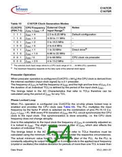
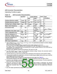
Table 10
C167CR Clock Generation Modes
CPU Frequency External Clock
f
CLKCFG
(P0H.7-5)
Notes
CPU = fOSC × F Input Range1)
1 1 1
1 1 0
1 0 1
1 0 0
0 1 1
0 1 0
0 0 1
fOSC × 4
fOSC × 3
fOSC × 2
fOSC × 5
fOSC × 1
fOSC × 1.5
2.5 to 8.25 MHz
3.33 to 11 MHz
5 to 16.5 MHz
2 to 6.6 MHz
1 to 33 MHz
Default configuration
–
–
–
Direct drive2)
6.66 to 22 MHz
2 to 66 MHz
–
f
OSC / 2
CPU clock via prescaler
0 0 0
fOSC × 2.5
4 to 13.2 MHz
–
1)
The external clock input range refers to a CPU clock range of 10 … 33 MHz (PLL operation).
2)
The maximum frequency depends on the duty cycle of the external clock signal.
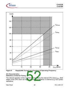
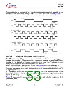
Prescaler Operation
When prescaler operation is configured (CLKCFG = 001B) the CPU clock is derived from
the internal oscillator (input clock signal) by a 2:1 prescaler.
The frequency of fCPU is half the frequency of fOSC and the high and low time of fCPU (i.e.
the duration of an individual TCL) is defined by the period of the input clock fOSC
.
The timings listed in the AC Characteristics that refer to TCLs therefore can be
calculated using the period of fOSC for any TCL.
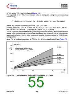
Phase Locked Loop
When PLL operation is configured (via CLKCFG) the on-chip phase locked loop is
enabled and provides the CPU clock (see Table 10). The PLL multiplies the input
frequency by the factor F which is selected via the combination of pins P0.15-13 (i.e.
f
CPU = fOSC × F). With every F’th transition of fOSC the PLL circuit synchronizes the CPU
clock to the input clock. This synchronization is done smoothly, i.e. the CPU clock
frequency does not change abruptly.
Due to this adaptation to the input clock the frequency of fCPU is constantly adjusted so
it is locked to fOSC. The slight variation causes a jitter of fCPU which also effects the
duration of individual TCLs.
The timings listed in the AC Characteristics that refer to TCLs therefore must be
calculated using the minimum TCL that is possible under the respective circumstances.
The actual minimum value for TCL depends on the jitter of the PLL. As the PLL is
constantly adjusting its output frequency so it corresponds to the applied input frequency
(crystal or oscillator) the relative deviation for periods of more than one TCL is lower than
Data Sheet
50
V3.2, 2001-07

 INFINEON [ Infineon ]