C167CR
C167SR
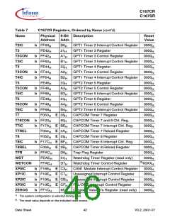
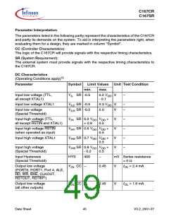
DC Characteristics (cont’d)
(Operating Conditions apply)1)
Parameter
Symbol
Limit Values Unit Test Condition
min.
VOH CC 2.4
0.9 VDD
max.
Output high voltage3)
(PORT0, PORT1, Port 4, ALE,
RD, WR, BHE, CLKOUT,
RSTOUT)
–
–
V
V
I
I
OH = -2.4 mA
OH = -0.5 mA
Output high voltage3)
(all other outputs)
V
OH1CC 2.4
0.9 VDD
OZ1 CC –
OZ2 CC –
–
V
V
I
I
OH = -1.6 mA
OH = -0.5 mA
–
Input leakage current (Port 5)
I
I
200
500
nA 0 V < VIN < VDD
Input leakage current
(all other)4)
nA 0.45 V < VIN < VDD
6)
RSTIN inactive current5)
RSTIN active current5)
READY/RD/WR inact. current8) IRWH
READY/RD/WR active current8) IRWL
ALE inactive current8)
ALE active current8)
Port 6 inactive current8)
Port 6 active current8)
IRSTH
–
-10
–
µA VIN = VIH1
7)
IRSTL
-100
–
µA VIN = VIL
6)
-40
–
µA VOUT = 2.4 V
µA VOUT = VOLmax
µA VOUT = VOLmax
µA VOUT = 2.4 V
µA VOUT = 2.4 V
µA VOUT = VOL1max
µA VIN = VIHmin
µA VIN = VILmax
µA 0 V < VIN < VDD
7)
-500
–
6)
IALEL
40
–
7)
IALEH
500
–
6)
IP6H
-40
–
7)
IP6L
-500
–
6)
PORT0 configuration current9) IP0H
-10
–
7)
IP0L
-100
XTAL1 input current
Pin capacitance10)
(digital inputs/outputs)
IIL CC –
CIO CC –
20
10
pF f = 1 MHz
TA = 25 °C
1)
Keeping signal levels within the levels specified in this table, ensures operation without overload conditions.
For signal levels outside these specifications also refer to the specification of the overload current IOV
.
2)
3)
Valid in bidirectional reset mode only.
This specification is not valid for outputs which are switched to open drain mode. In this case the respective
output will float and the voltage results from the external circuitry.
4)
5)
6)
7)
This parameter is not valid for pins READY, ALE, RD, and WR while the respective pull device is on.
These parameters describe the RSTIN pullup, which equals a resistance of ca. 50 to 250 kΩ.
The maximum current may be drawn while the respective signal line remains inactive.
The minimum current must be drawn in order to drive the respective signal line active.
Data Sheet
46
V3.2, 2001-07

 INFINEON [ Infineon ]