IMW120R140M1H
CoolSiC™ 1200V SiC Trench MOSFET
Maximum ratings
1
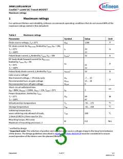
Maximum ratings
For optimum lifetime and reliability, Infineon recommends operating conditions that do not exceed 80% of the
maximum ratings stated in this datasheet.
Table 2
Maximum ratings
Parameter
Symbol
Value
Unit
V
Drain-source voltage, Tvj ≥ 25°C
VDSS
1200
DC drain current for Rth(j-c,max), limited by Tvjmax, VGS = 18V,
TC = 25°C
TC = 100°C
ID
19
13
A
A
1
Pulsed drain current, tp limited by Tvjmax, VGS = 18V
ID,pulse
32
DC body diode forward current for Rth(j-c,max)
,
limited by Tvjmax, VGS = 0V
TC = 25°C
TC = 100°C
ISD
A
A
V
21
12
1
Pulsed body diode current, tp limited by Tvjmax
Gate-source voltage2
ISD,pulse
32
Max transient voltage, < 1% duty cycle
Recommended turn-on gate voltage
Recommended turn-off gate voltage
Short-circuit withstand time
VDD = 800V, VDS,peak < 1200V, VGS,on = 15V, Tj,start = 25°C
Power dissipation, limited by Tvjmax
TC = 25°C
VGS
VGS,on
VGS,off
-7… 23
15… 18
0
µs
W
tSC
3
Ptot
94
47
TC = 100°C
°C
°C
Virtual junction temperature
Storage temperature
Tvj
-55… 175
-55… 150
Tstg
Soldering temperature,
wave soldering only allowed at leads,
1.6mm (0.063 in.) from case for 10 s
Mounting torque, M3 screw
Tsold
260
0.6
°C
M
Nm
Maximum of mounting processes: 3
1 verified by design
2 Important note: The selection of positive and negative gate-source voltages impacts the long-term behavior
of the device. The design guidelines described in Application Note AN2018-09 must be considered to ensure
sound operation of the device over the planned lifetime.
Datasheet
3 of 17
2.2
2020-12-11

 INFINEON [ Infineon ]