Control Integrated POwer System (CIPOS™)
IFCM15P60GD
Circuit of a Typical Application
#1
RG
PFC
gate
driver
IC
GX (24)
NX (23)
X (22)
VDD line
RGE
CGE
#4
(1) VS(U)
(2) VB(U)
VB1
#8
#7
RBS1
HO1
VS1
#4
(3) VS(V)
(4) VB(V)
VB2
P (21)
RBS2
HO2
VS2
#4
(5) VS(W)
(6) VB(W)
VB3
~
AC
HO3
VS3
U (20)
RBS3
#1
(7) HIN(U)
HIN1
#5
(8) HIN(V)
Micro
Controller
HIN2
LO1
LO2
(9) HIN(W)
V (19)
W (18)
N (17)
3-ph AC
Motor
HIN3
(10) LIN(U)
LIN1
(11) LIN(V)
LIN2
(12) LIN(W)
LIN3
(13) VDD
VDD
#9
VDD line
(14) VFO
VFO
(15) ITRIP
ITRIP
LO3
(16) VSS
5 or 3.3V line
VSS
#6
#3
#7
<Signal for protection>
#2
Current sensing
Input surge voltage sensing
<Signal for protection>
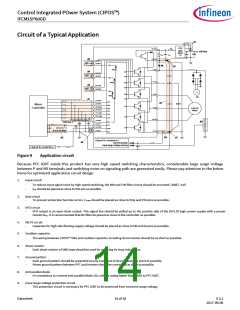
Figure 9
Application circuit
Because PFC IGBT inside this product has very high speed switching characteristics, considerable large surge voltage
between P and NX terminals and switching noise on signaling path are generated easily. Please pay attention to the below
items for optimized application circuit design.
1.
Input circuit
-
-
To reduce input signal noise by high speed switching, the RIN and CIN filter circuit should be mounted. (100Ω, 1nF)
CIN should be placed as close to VSS pin as possible.
2.
3.
Itrip circuit
-
To prevent protection function errors, CITRIP should be placed as close to Itrip and VSS pins as possible.
VFO circuit
-
VFO output is an open drain output. This signal line should be pulled up to the positive side of the 5V/3.3V logic power supply with a proper
resistor RPU. It is recommended that RC filter be placed as close to the controller as possible.
4.
5.
VB-VS circuit
-
Capacitor for high side floating supply voltage should be placed as close to VB and VS pins as possible.
Snubber capacitor
-
The wiring between CIPOS™ Mini and snubber capacitor including shunt resistor should be as short as possible.
6.
7.
Shunt resistor
-
Each shunt resistor of SMD type should be used for reducing its stray inductance.
Ground pattern
-
Each ground pattern should be separated at only one point of shunt resistor as short as possible.
-
Power ground pattern between PFC and Inverter should be connected as short as possible.
8.
9.
Anti parallel diode
-
It’s mandatory to connect anti-parallel diode (2A, voltage rating higher than 650V) to PFC IGBT.
Input surge voltage protection circuit
-
This protection circuit is necessary for PFC IGBT to be protected from excessive surge voltage.
Datasheet
14 of 18
V 2.2
2017-09-06

 INFINEON [ Infineon ]