F3
ICE3AS02 / ICE3AS02G / ICE3BS02 / ICE3BS02G
Functional Description
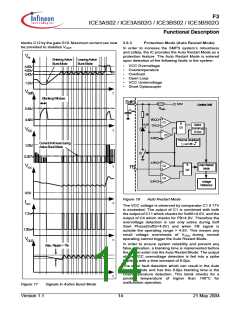
blocks C12 by the gate G10. Maximum current can now 3.6.3
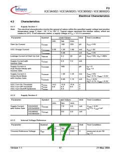
Protection Mode (Auto Restart Mode)
be provided to stabilize VOUT
.
In order to increase the SMPS system’s robustness
and safety, the IC provides the Auto Restart Mode as a
protection feature. The Auto Restart Mode is entered
upon detection of the following faults in the system:
V
FB
Entering Active Leaving Active
Burst Mode
Burst Mode
•
•
•
•
•
•
VCC Overvoltage
Overtemperature
Overload
Open Loop
VCC Undervoltage
Short Optocoupler
4.80V
4.00V
3.40V
1.32V
V
SoftS
t
Blanking Window
SoftS
6.5V
Control Unit
RSoftS
5.40V
4.40V
CSoftS
5k
VCC
C1
&
G1
4.4V
Spike
17V
Blanking
V
t
t
t
t
t
CS
8.0us
C11
4.0V
Thermal Shutdown
T >140°C
Current limit level during
ActiveBurst Mode
j
1.00V
S1
0.257V
4.8V
5.4V
&
Auto Restart
Mode
C4
C3
V
VCC
FB
G5
Voltage
Reference
8.5V
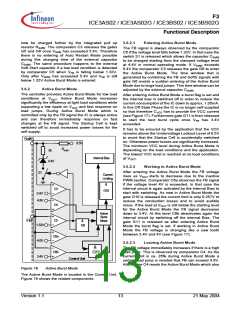
Figure 18
Auto Restart Mode
IVCC
The VCC voltage is observed by comparator C1 if 17V
is exceeded. The output of C1 is combined with both
the output of C11 which checks for SoftS<4.0V, and the
output of C4 which checks for FB>4.8V. Therefore the
overvoltage detection is can only active during Soft
Start Phase(SoftS<4.0V) and when FB signal is
outside the operating range > 4.8V. This means any
small voltage overshoots of VVCC during normal
operating cannot trigger the Auto Restart Mode.
7.2mA
1.05mA
VOUT
In order to ensure system reliability and prevent any
false activation, a blanking time is implemented before
the IC can enter into the Auto Restart Mode. The output
of the VCC overvoltage detection is fed into a spike
blanking with a time constant of 8.0µs.
Max. Ripple < 1%
The other fault detection which can result in the Auto
Restart Mode and has this 8.0µs blanking time is the
Overtemperature detection. This block checks for a
junction temperature of higher than 140°C for
malfunction operation.
Figure 17
Signals in Active Burst Mode
Version 1.1
14
21 May 2004

 INFINEON [ Infineon ]