F3
ICE3AS02 / ICE3AS02G / ICE3BS02 / ICE3BS02G
Functional Description
now be charged further by the integrated pull up 3.6.2.1
Entering Active Burst Mode
resistor RSoftS. The comparator C3 releases the gates
G5 and G6 once VSofts has exceeded 5.4V. Therefore
there is no entering of Auto Restart Mode possible
during this charging time of the external capacitor
The FB signal is always observed by the comparator
C5 if the voltage level falls below 1.32V. In that case the
switch S1 is released which allows the capacitor CSoftS
to be charged starting from the clamped voltage level
at 4.4V in normal operating mode. If VSoftS exceeds
5.4V the comparator C3 releases the gate G6 to enter
the Active Burst Mode. The time window that is
generated by combining the FB and SoftS signals with
gate G6 avoids a sudden entering of the Active Burst
Mode due to large load jumps. This time window can be
C
SoftS. The same procedure happens to the external
Soft Start capacitor if a low load condition is detected
by comparator C5 when VFB is falling below 1.32V.
Only after VSoftS has exceeded 5.4V and VFB is still
below 1.32V Active Burst Mode is entered.
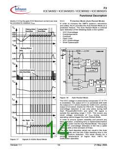
3.6.2
The controller provides Active Burst Mode for low load
conditions at VOUT Active Burst Mode increases
Active Burst Mode
adjusted by the external capacitor CSoftS
.
After entering Active Burst Mode a burst flag is set and
the internal bias is switched off in order to reduce the
current consumption of the IC down to approx. 1.05mA.
In this Off State Phase the IC is no longer self supplied
so that therefore CVCC has to provide the VCC current
(see Figure 17). Furthermore gate G11 is then released
to start the next burst cycle once VFB has 3.4V
exceeded.
.
significantly the efficiency at light load conditions while
supporting a low ripple on VOUT and fast response on
load jumps. During Active Burst Mode which is
controlled only by the FB signal the IC is always active
and can therefore immediately response on fast
changes at the FB signal. The Startup Cell is kept
switched off to avoid increased power losses for the
self supply.
It has to be ensured by the application that the VCC
remains above the Undervoltage Lockout Level of 8.5V
to avoid that the Startup Cell is accidentally switched
on. Otherwise power losses are significantly increased.
The minimum VCC level during Active Burst Mode is
depending on the load conditions and the application.
The lowest VCC level is reached at no load conditions
SoftS
6.5V
RSoftS
5k
Internal Bias
4.4V
at VOUT
.
3.6.2.2
Working in Active Burst Mode
After entering the Active Burst Mode the FB voltage
rises as VOUT starts to decrease due to the inactive
PWM section. Comparator C6a observes the FB signal
if the voltage level 4V is exceeded. In that case the
internal circuit is again activated by the internal Bias to
start with switching. As now in Active Burst Mode the
gate G10 is released the current limit is only 0.257V to
reduce the conduction losses and to avoid audible
noise. If the load at VOUT is still below the starting level
for the Active Burst Mode the FB signal decreases
down to 3.4V. At this level C6b deactivates again the
internal circuit by switching off the internal Bias. The
gate G11 is released as after entering Active Burst
Mode the burst flag is set. If working in Active Burst
Mode the FB voltage is changing like a saw tooth
between 3.4V and 4V (see Figure 17).
S1
Current
Limiting
&
C3
G10
5.4V
4.8V
C4
Active
Burst
C5
C6a
C6b
Mode
FB
&
G6
1.32V
4.0V
3.4V
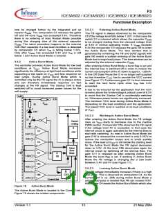
3.6.2.3
Leaving Active Burst Mode
&
The FB voltage immediately increases if there is a high
load jump. This is observed by comparator C4. As the
current limit is ca. 26% during Active Burst Mode a
certain load jump is needed that FB can exceed 4.8V.
At this time C4 resets the Active Burst Mode which also
G11
Control Unit
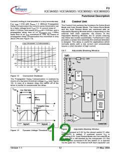
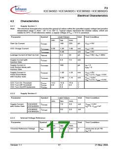
Figure 16
Active Burst Mode
The Active Burst Mode is located in the Control Unit.
Figure 16 shows the related components.
Version 1.1
13
21 May 2004

 INFINEON [ Infineon ]