F3
ICE3AS02 / ICE3AS02G / ICE3BS02 / ICE3BS02G
Electrical Characteristics
4.3
Characteristics
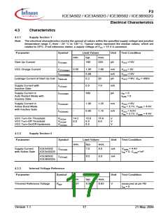
4.3.1
Supply Section 1
Note: The electrical characteristics involve the spread of values within the specified supply voltage and junction
temperature range TJ from – 25 ° C to 130 ° C. Typical values represent the median values, which are
related to 25°C. If not otherwise stated, a supply voltage of VCC = 15 V is assumed.
Parameter
Symbol
Limit Values
Unit
Test Condition
min.
typ.
max.
Start Up Current
IVCCstart
-
160
220
µA
VVCC =14V
VCC Charge Current
IVCCcharge1 0.55
1.05
0.88
0.2
1.60
-
mA
mA
µA
VVCC = 0V
IVCCcharge2
Leakage Current of Start Up Cell IStartLeak
-
-
VVCC =14V
20
VVCC =16V, VHV = 450V
Supply Current with
Inactive Gate
IVCCsup1
-
-
5.5
7.0
-
mA
Supply Current in
Auto Restart Mode with
Inactive Gate
IVCCrestart
300
µA
IFB = 0
ISofts = 0
Supply Current in
Active Burst Mode
with Inactive Gate
IVCCburst1
IVCCburst2
-
-
1.05
0.95
1.25
1.15
mA
mA
VVCC =15V
VFB = 3.7V, VSoftS = 4.4V
VVCC = 9.5V
VFB = 3.7V, VSoftS = 4.4V
VCC Turn-On Threshold
VCC Turn-Off Threshold
VCC Turn-On/Off Hysteresis
VVCCon
VVCCoff
VVCChys
14.2
8.0
-
15.0
8.5
6.5
15.8
9.0
-
V
V
V
4.3.2
Supply Section 2
Parameter
Symbol
Limit Values
Unit
Test Condition
min.
typ.
max.
Supply Current
with Active Gate
ICE3AS02
IVCCsup2
IVCCsup2
-
7.0
8.5
mA
mA
VSoftS = 4.4V
IFB = 0, CLoad=1nF
ICE3AS02G
ICE3BS02
-
6.5
8.0
ICE3BS02G
4.3.3
Internal Voltage Reference
Symbol
Parameter
Limit Values
Unit
Test Condition
min.
typ.
max.
6.63
Trimmed Reference Voltage
VREF
6.37
6.50
V
measured at pin FB
IFB = 0
Version 1.1
17
21 May 2004

 INFINEON [ Infineon ]