F3
ICE3AS02 / ICE3AS02G / ICE3BS02 / ICE3BS02G
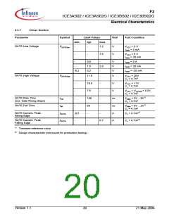
Electrical Characteristics
4
Electrical Characteristics
Note: All voltages are measured with respect to ground (Pin 8). The voltage levels are valid if other ratings are
not violated.
4.1
Absolute Maximum Ratings
Note: Absolute maximum ratings are defined as ratings, which when being exceeded may lead to destruction
of the integrated circuit. For the same reason make sure, that any capacitor that will be connected to pin 7
(VCC) is discharged before assembling the application circuit.
Parameter
Symbol
Limit Values
Unit
Remarks
min.
max.
500V
22
HV Voltage
VHV
-
V
VCC Supply Voltage
FB Voltage
VVCC
VFB
-0.3
-0.3
-0.3
-0.3
-0.3
-40
-55
-
V
6.5
V
SoftS Voltage
VSoftS
VGate
VCS
6.5
V
Gate Voltage
22
V
Internally clamped at 11.5V
CS Voltage
6.5
V
Junction Temperature
Storage Temperature
Total Power Dissipation
Tj
150
150
0.45
0.90
185
90
° C
° C
W
W
K/W
K/W
kV
TS
PtotDSO8
PtotDIP8
RthJADSO8
RthJADIP8
VESD
P-DSO-8-8, Tamb < 50°C
PG-DIP-8-6, Tamb < 50°C
P-DSO-8-8
-
Thermal Resistance
Junction-Ambient
-
-
PG-DIP-8-6
ESD Capability(incl. HV Pin)
-
3
Human body model1)
1)
According to EIA/JESD22-A114-B (discharging a 100pF capacitor through a 1.5kΩ series resistor)
4.2
Operating Range
Note: Within the operating range the IC operates as described in the functional description.
Parameter
Symbol
Limit Values
Unit
Remarks
min.
max.
20
VCC Supply Voltage
VVCC
TjCon
VVCCoff
-25
V
Junction Temperature of
Controller
130
°C
Max value limited due to thermal
shut down of controller
Version 1.1
16
21 May 2004

 INFINEON [ Infineon ]