Quasi-Resonant, 800V CoolSET™ in DS0-12 Package
Electrical Characteristics
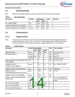
4.2
Operating Range
Note:
Within the operating range the IC operates as described in the functional description.
Table 5
Operating Range
Parameter
Symbol
Unit
Remarks
Limit Values
min.
max.
VCC Supply Voltage
VVCC
VVCCoff
VVCCOVP
130
V
Junction Temperature of Controller
Junction Temperature of CoolMOS™
TjCon
-40
-40
°C
°C
TjCoolMOS
150
4.3
Characteristics
Supply Section
4.3.1
Note:
The electrical characteristics involve the spread of values within the specified supply voltage and
junction temperature range TJ from – 40 °C to 125 °C. Typical values represent the median values,
which are related to 25°C. If not otherwise stated, a supply voltage of VCC = 17 V is assumed.
Table 6
Supply Section
Parameter
Symbol
Unit Test Condition
Limit Values
min. typ.
max.
Start Up Current
IVCCstart
-
-
300
1.22
1.1
1
550
μ A
mA
mA
mA
mA
VVCC =VVCCon -0.2 V
VVCC = 0 V
VCC Charge Current
IVCCcharge1
5
-
IVCCcharge2 0.8
VVCC = 1 V
IVCCcharge3
IDrainIn
-
-
-
VVCC =VVCCon -0.2 V
VVCC =VVCCon -0.2 V
Maximum Input Current of Startup Cell
-
2
and CoolMOS™
Leakage Current of
IDrainLeak
-
0.2
50
μ A
VDrain = 650 V at Tj=100 °C
Startup Cell and CoolMOS™
Supply Current in normal operation
IVCCNM
IVCCAR
-
-
1.5
2.3
-
mA
output low
Supply Current in
300
μ A
IFB = 0 A
Auto Restart Mode with Inactive Gate
Supply Current in Latch-off Mode
IVCClatch
IVCCburst
-
-
300
500
-
μ A
μ A
Supply Current in Burst Mode with
inactive Gate
VFB = 2.5 V, exclude the
current flowing out from
FB pin
950
VCC Turn-On Threshold
VCC Turn-Off Threshold
VCC Turn-On/Off Hysteresis
VVCCon
VVCCoff
VVCChys
17.0
9.8
-
18.0
10.5
7.5
19.0
11.2
-
V
V
V
Data Sheet
14
Revision 1.0
2016-05-12

 INFINEON [ Infineon ]