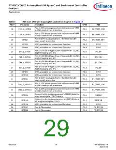
EZ-PD™ CCG7D Automotive USB Type-C and Buck-boost Controller
Dual-port
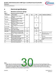
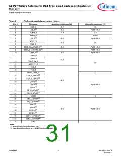
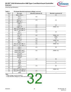
Electrical specifications
6.2
Device-level specifications
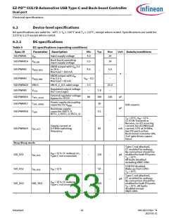
All specifications are valid for –40°C TA 105°C and TJ 125°C, except where noted. Specifications are valid for
3.0 V to 5.5 V except where noted.
6.2.1
DC specifications
Table 9
DC specifications (operating conditions)
Min
Typ
Max
Unit
Spec ID
SID.PWR#1
Parameter Description
Details/conditions
V
Input supply voltage
4.0
24
IN
Buck boost operating
input supply voltage
SID.PWR#1A
V
5.5
24
IN_BB
VDDD output with V 5.5
IN
SID.PWR#2
V
to 24 V,
4.6
5.5
DDD_REG
–
Max load = 150 mA
V
–
VDDD output with V
4 to 5.5 V,
IN
SID.PWR#3
V
V – 0.2
–
DDD_MIN
IN
Max load = 20 mA
SID.PWR#20 VBUS
VBUS_C_0/1 valid range
3.3
–
21.5
–
Regulated output voltage
(for Core Logic)
SID.PWR#5
SID.PWR#16
SID.PWR#17
V
1.8
100
10
CCD
External regulator voltage
bypass for VCCD
C
C
80
120
nF
µF
EFC_VCCD
EXC_VDDD
Power supply decoupling
capacitor for V
X5R ceramic
DDD
Bootstrap supply
SID.PWR#18
C
capacitor (BST1_0,
BST1_1, BST2_0, BST2_1)
0.1
EXV
T = 25°C, V = 12 V.
A
IN
–
–
CC IO IN Transmit or
Receive, no I/O sourcing
current, No VCONN load
Supply current at
0.4 MHz switching
frequency
SID.PWR#24
I
85
mA current, CPU at 24 MHz,
two PD ports active.
Buck-boost converter ON,
3-nF gate driver capaci-
tance.
DD_ACT
Deep Sleep mode
Type-C not attached,
CC enabled for wakeup.
Rp connection should be
µA enabled for both PD ports.
V
= 12 V. CC wakeup on,
IN
SID_DS1
SID_DS2
SID_DS3
I
I
–
–
110
50
–
–
DD_DS1
DD_DS2
Type-C not connected.
T = 25°C.
A
All faults disabled
including VBAT-GND.
USB-PD disabled.
V
= 12 V
Wake-up from GPIO.
IN
T = 25°C.
A
Type-C not attached,
CC enabled for wakeup.
Rp connection should be
enabled for both PD ports.
µA
V
= 12 V. CC wakeup on,
IN
IDD_DS3
450
Type-C not connected.
T = 25°C. All faults
A
disabled except
VBAT-GND.
Datasheet
33
002-28172 Rev. *N
2023-01-31

 INFINEON [ Infineon ]