EZ-PD™ CCG7D Automotive USB Type-C and Buck-boost Controller
Dual-port
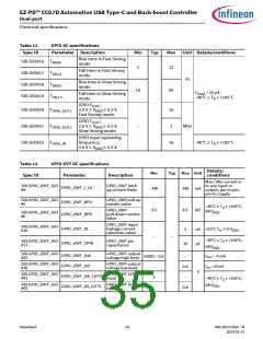
Electrical specifications
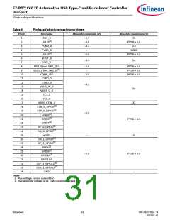
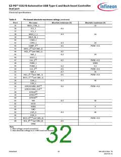
Table 8
Pin based absolute maximum ratings
Pin #
Pin name
Absolute minimum (V)
Absolute maximum (V)
1
SW1_0
–0.7
–0.5
–0.3
–
35
[2]
2
LG1_0
PVDD + 0.5
0.3
3
PGND_0
PVDD_0
4
VDDD
[2]
5
LG2_0
–0.5
PVDD + 0.5
6
VOUT_0
SW2_0
–0.3
24
7
[2]
[2]
8
HG2_0 (wrt SW2_0)
–0.5
–
PVDD + 0.5
PVDD + 0.5
PVDD + 0.5
9
BST2_0 (wrt SW2_0)
[2]
10
11
12
13
14
15
16
17
18
19
20
21
22
23
24
25
26
27
28
29
30
31
32
33
34
COMP_0
–0.5
CSPO_0
CSNO_0
–0.3
–0.5
VBUS_IN_0
VBUS_C_0
CC1_0
24
32
CC2_0
VBUS_CTRL_0
[2]
CSN_0_GPIO0
[2]
CSP_0_GPIO1
[2]
GPIO2
[2]
GPIO3
PVDD + 0.5
[2]
GPIO4
[2]
DP_0_GPIO5
[2]
DM_0_GPIO6
VDDD
–
–0.5
–
6
[2]
DM_1_GPIO7
[2]
DP_1_GPIO8
[2]
XRES
[2]
GPIO9
PVDD + 0.5
[2]
GPIO10
[2]
GPIO11
[2]
CSP_1_GPIO12
[2]
CSN_1_GPIO13
GND
–
Note
2. Max voltage cannot exceed 6 V.
3. Max absolute voltage w.r.t. GND must not exceed 40 V.
Datasheet
31
002-28172 Rev. *N
2023-01-31

 INFINEON [ Infineon ]