EZ-PD™ CCG7D Automotive USB Type-C and Buck-boost Controller
Dual-port
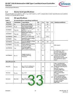
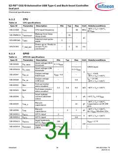
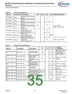
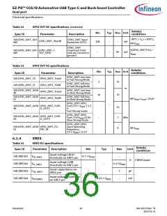
Electrical specifications
6.3
Digital peripherals
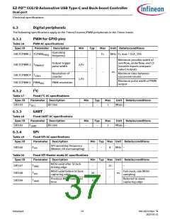
The following specifications apply to the Timer/Counter/PWM peripherals in the Timer mode.
6.3.1
Table 16
PWM for GPIO pins
PWM AC specifications
Parameter Description
Operating
Spec ID
Min
Typ
Max Unit Details/conditions
SID.TCPWM.1 TCPWMFREQ
–
Fc
MHz Fc max = CLK_SYS
frequency
Minimum possible width of
overflow, underflow, and CC
(counter equals compare
value) outputs
Minimum time between
successive counts
Output trigger
pulse width
SID.TCPWM.3 TPWMEXT
2/Fc
1/Fc
–
–
ns
Resolution of
counter
SID.TCPWM.4 TCRES
Minimum pulse width of PWM
output
SID.TCPWM.5 PWMRES
PWM resolution
6.3.2
I2C
Table 17
Spec ID
SID153
Fixed I2C AC specifications
Parameter Description
Min
Typ
Max
Unit Details/conditions
FI2C1
Bit rate
–
–
1
Mbps –
6.3.3
UART
Table 18
Spec ID
SID162
Fixed UART AC specifications
Parameter Description
Min
–
Typ
–
Max
1
Unit Details/conditions
Mbps –
FUART
Bit rate
6.3.4
SPI
Table 19
Fixed SPI AC specifications
Spec ID
Parameter Description
Min Typ Max Unit Details/conditions
MHz –
SPI operating frequency
(Master; 6X oversampling)
SID166
FSPI
–
–
8
Table 20
Spec ID
Fixed SPI Master mode AC specifications
Parameter Description
Min Typ Max Unit Details/conditions
MOSI valid after SClock
SID167
SID168
SID169
TDMO
–
20
0
15
–
driving edge
MISO valid before SClock
capturing edge
Full clock, late MISO
sampling
Referred to slave
capturing edge
TDSI
–
ns
–
Previous MOSI data hold
THMO
time
Datasheet
37
002-28172 Rev. *N
2023-01-31

 INFINEON [ Infineon ]