EZ-PD™ CCG7D Automotive USB Type-C and Buck-boost Controller
Dual-port
Electrical specifications
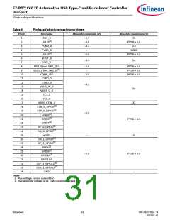
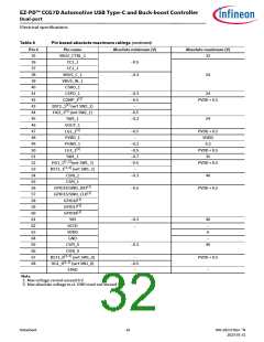
Table 8
Pin based absolute maximum ratings (continued)
Pin #
Pin name
VBUS_CTRL_1
CC2_1
Absolute minimum (V)
Absolute maximum (V)
35
36
37
38
39
40
41
42
43
44
45
46
47
48
49
50
51
52
53
54
55
56
57
58
59
60
61
62
63
64
65
66
67
68
32
–0.5
–0.3
CC1_1
VBUS_C_1
VBUS_IN_1
CSNO_1
24
CSPO_1
–0.3
–0.5
–
24
[1]
COMP_1
PVDD + 0.5
[1]
BST2_1 (wrt SW2_1)
[1]
HG2_1 (wrt SW2_1)
–0.5
–0.3
SW2_1
24
VOUT_1
[1]
LG2_1
–0.5
–
PVDD + 0.5
VDDD
PVDD_1
PGND_1
–0.3
–0.5
–0.7
–0.5
–
0.3
[1]
LG1_1
PVDD + 0.5
35
SW1_1
[1, 2]
HG1_1
(wrt SW1_1)
(wrt SW1_1)
PVDD + 0.5
[1, 2]
BST1_1
CSNI_1
CSPI_1
–0.3
40
[1]
[1]
GPIO14/SWD_DAT
GPIO15/SWD_CLK
–0.5
PVDD + 0.5
[1]
GPIO16
[1]
GPIO17
[1]
GPIO18
VIN
VCCD
VDDD
GND
–0.3
–
40
–
6
–
CSPI_0
–0.3
40
CSNI_0
[1, 2]
BST1_0
(wrt SW1_0)
(wrt SW1_0)
–
–0.5
–
PVDD + 0.5
–
[1, 2]
HG1_0
EPAD
Note
2. Max voltage cannot exceed 6 V.
3. Max absolute voltage w.r.t. GND must not exceed 40 V.
Datasheet
32
002-28172 Rev. *N
2023-01-31

 INFINEON [ Infineon ]