™
PROFET + 24V
BTT6200-4ESA
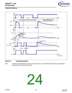
Protection functions
6
Protection functions
The device provides integrated protection functions. These functions are designed to prevent the destruction of
the IC from fault conditions described in the data sheet. Fault conditions are considered as “outside” normal
operating range. Protection functions are designed for neither continuous nor repetitive operation.
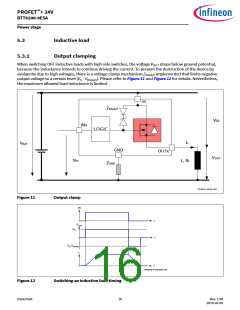
6.1
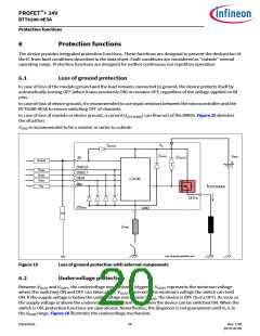
Loss of ground protection
In case of loss of the module ground and the load remains connected to ground, the device protects itself by
automatically turning OFF (when it was previously ON) or remains OFF, regardless of the voltage applied on IN
pins.
In case of loss of device ground, it’s recommended to use input resistors between the microcontroller and the
BTT6200-4ESA to ensure switching OFF of channels.
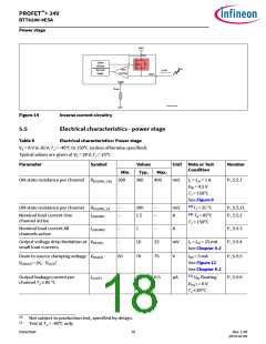
In case of loss of module or device ground, a current (IOUT(GND)) can flow out of the DMOS. Figure 15 sketches
the situation.
ZGND is recommended to be a resistor in series to a diode .
ZIS(AZ)
VS
ZD(AZ)
VBAT
ZDS(AZ)
IS
RSENSE
DSEL0
DSEL1
DEN
RDSEL
RDSEL
RDEN
LOGIC
INx
RIN
IOUT(GND)
OUTx
ZDESD
GND
RIS
IS
ZGND
Loss of ground protection.vsd
Figure 15
Loss of ground protection with external components
6.2
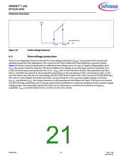
Undervoltage protection
Between VS(UV) and VS(OP), the undervoltage mechanism is triggered. VS(OP) represents the minimum voltage
where the switching ON and OFF can takes place. VS(UV) represents the minimum voltage the switch can hold
ON. If the supply voltage is below the undervoltage mechanism VS(UV), the device is OFF (turns OFF). As soon as
the supply voltage is above the undervoltage mechanism VS(OP), then the device can be switched ON. When the
switch is ON, protection functions are operational. Nevertheless, the diagnosis is not guaranteed until VS is in
the VNOM range. Figure 16 illustrates the undervoltage mechanism.
Datasheet
20
Rev. 1.00
2019-03-09

 INFINEON [ Infineon ]