High Current PN Half Bridge
BTN8982TA
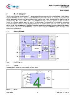
General Product Characteristics
Note:Stresses above the ones listed here may cause permanent damage to the device. Exposure to absolute
maximum rating conditions for extended periods may affect device reliability.
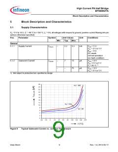
Note:Integrated protection functions are designed to prevent IC destruction under fault conditions described in the
data sheet. Fault conditions are considered as “outside” normal operating range. Protection functions are
not designed for continuous repetitive operation.
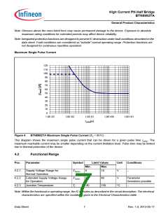
Maximum Single Pulse Current
120
110
100
90
80
70
60
50
40
30
20
10
0
1,0E-03
1,0E-02
1,0E-01
1,0E+00
1,0E+01
t pulse[s]
Figure 4
BTN8982TA Maximum Single Pulse Current (TC < 85°C)
This diagram shows the maximum single pulse current that can be driven for a given pulse time tpulse. The
maximum reachable current may be smaller depending on the current limitation level. Pulse time may be limited
due to thermal protection of the device.
4.2
Functional Range
Pos.
Parameter
Symbol
Limit Values
Unit
Conditions
Min.
Max.
4.2.1
4.2.2
4.2.3
Supply Voltage Range for
Normal Operation
VS(nor)
VS(ext)
Tj
8
18
V
–
Extended Supply Voltage Range
for Operation
5.5
-40
40
V
Parameter
Deviations possible
Junction Temperature
150
°C
–
Note:Within the functional or operating range, the IC operates as described in the circuit description. The electrical
characteristics are specified within the conditions given in the Electrical Characteristics table.
Data Sheet
7
Rev. 1.0, 2013-05-17

 INFINEON [ Infineon ]