High Current PN Half Bridge
BTN8982TA
Pin Configuration
3
Pin Configuration
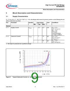
3.1
Pin Assignment
8
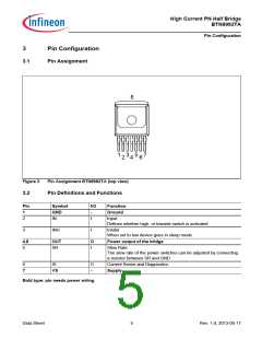
3 5
1
7
2 4 6
Figure 3
Pin Assignment BTN8982TA (top view)
3.2
Pin Definitions and Functions
Pin
1
Symbol
GND
IN
I/O
Function
Ground
Input
-
2
I
Defines whether high- or lowside switch is activated
3
INH
I
Inhibit
When set to low device goes in sleep mode
4,8
OUT
O
Power output of the bridge
5
SR
I
Slew Rate
The slew rate of the power switches can be adjusted by connecting
a resistor between SR and GND
6
IS
O
Current Sense and Diagnostics
7
VS
-
Supply
Bold type: pin needs power wiring
Data Sheet
5
Rev. 1.0, 2013-05-17

 INFINEON [ Infineon ]