High Current PN Half Bridge
BTN8982TA
Block Description and Characteristics
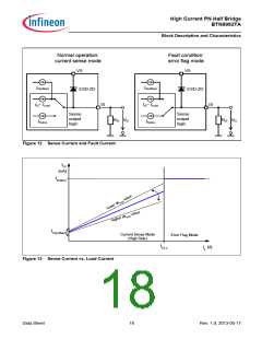
5.4.6
Electrical Characteristics - Control and Diagnostics
VS = 8 V to 18 V, Tj = -40 °C to +150 °C, all voltages with respect to ground, positive current flowing into pin
(unless otherwise specified)
Pos.
Parameter
Symbol
Limit Values
Unit
Conditions
Min.
Typ.
Max.
Control Inputs (IN and INH)
VINH(H)
VIN(H)
5.4.1
5.4.2
5.4.3
High level Voltage
INH, IN
–
–
1.75
1.6
2.15
2
V
–
VINH(L)
VIN(L)
Low level Voltage
INH, IN
1.1
1.4
–
V
–
1)
VINHHY
VINHY
Input Voltage hysteresis
–
–
350
200
–
–
mV
IINH(H)
IIN(H)
IINH(L)
IIN(L)
5.4.4
5.4.5
Input Current high level
Input Current low level
10
30
150
µA
µA
VIN = VINH = 5.3 V
VIN = VINH = 0.4 V
10
25
125
Current Sense
5.4.6
5.4.7
Differential Current Sense ratio dkILIS
in static on-condition
dkILIS = dIL / dIIS
103
mA
RIS = 1 kΩ
IL1 = 10 A
IL2 = 40 A
14
4
19.5
5
25
Maximum analog Sense Current, IIS(lim)
Sense Current in fault Condition
6.5
VS = 13.5 V
RIS = 1kΩ
5.4.8
5.4.9
Isense Leakage current
Isense offset current
IISL
–
–
1
µA
µA
VINH = 0 V
IIS(offset) 30
170
385
VS = 18V; VINH = 5 V
ISD(HS) = 0 A
1) Not subject to production test, specified by design
T = -40°C
j
T = 25°C
j
T = 150°C
j
VS [V]
T [°C]
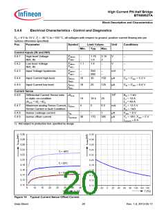
Figure 14 Typical Current Sense Offset Current
Data Sheet
20
Rev. 1.0, 2013-05-17

 INFINEON [ Infineon ]