High Current PN Half Bridge
BTN8982TA
Application Information
Reverse Polarity
Protection
Microcontroller
Voltage Regulator
(IPD90P03P4L-04)
I/O
WO
TLE
4278G
Reset
RO
Q
I
VS
L
1
DZ1
10V
CI
470nF
Vdd
XC866
CQ
22µF
D
GND
Vss
C
100nF
1
R
10kΩ
3
CD
47nF
I/O I/O
I/O
R2
10kΩ
BTN8982TA
C9
100nF
C10
1000µF
CO 2V
220nF
VS
R1
10kΩ
INH
OUT
IN
M
C
220nF
OUT
IS
CIS
1nF
SR
R12
GND
1k Ω
R11
0..51kΩ
C
100nF
2
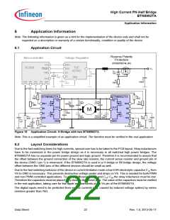
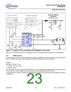
Figure 17 Application Circuit: Half-Bridge with a BTN8982TA (Load to GND)
Note:This is a simplified example of an application circuit. The function must be verified in the real application.
6.3
PWM Control
For the selection of the max. PWM frequency the choosen rise/fall-time and the requirements on the duty cycle
have to be taken into account. We recommend a PWM-period at least 10 times the rise-time.
Example:
Rise-time = fall-time = 4µs.
=> T-PWM = 10 * 4µs = 40µs.
=> f-PWM = 25kHz.
The min. and max. value of the duty cycle (PWM ON to OFF percentage) is determined by the real fall time plus
the real rise time. In this example a duty cycle make sense from approximately 20% to 80%.
If a wider duty cycle range is needed, the PWM frequency could be decreased and/or the rise/fall-time could be
accelerated.
Data Sheet
23
Rev. 1.0, 2013-05-17

 INFINEON [ Infineon ]