High Current PN Half Bridge
BTN8982TA
Block Description and Characteristics
compared to driving the MOSFET in linear mode. Therefore it is possible to use the current limitation for a short
time without exceeding the maximum allowed junction temperature (e.g. for limiting the inrush current during motor
start up). However, the regular use of the current limitation is allowed as long as the specified maximum junction
temperature is not exceeded. Exceeding this temperature can reduce the lifetime of the device.
5.3.4
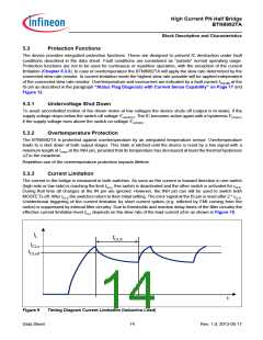
Short Circuit Protection
The device provides embedded protection functions against
•
•
•
output short circuit to ground
output short circuit to supply voltage
short circuit of load
The short circuit protection is realized by the previously described current limitation in combination with the over-
temperature shut down of the device.
5.3.5
Electrical Characteristics - Protection Functions
VS = 8 V to 18 V, Tj = -40 °C to +150 °C, all voltages with respect to ground, positive current flowing into pin
(unless otherwise specified)
Pos.
Parameter
Symbol
Limit Values
Unit
Conditions
Min.
Typ.
Max.
Under Voltage Shut Down
5.3.1
5.3.2
5.3.3
Switch-ON Voltage
Switch-OFF Voltage1)
ON/OFF Hysteresis
VUV(ON)
VUV(OFF)
VUV(HY)
–
–
5.5
4.5
–
V
V
V
VS increasing
3.0
–
–
VS decreasing, INH = 1
2)
0.2
Current Limitation
5.3.4
Current Limitation Detection level ICLH0
High Side
55
55
77
77
98
98
A
A
VS = 13.5 V
VS = 13.5 V
5.3.5
Current Limitation Detection level ICLL0
Low Side
Current Limitation Timing
5.3.6
Shut OFF Time for HS and LS
tCLS
70
115
210
µs
VS = 13.5 V; 2)
Thermal Shut Down
5.3.7
5.3.8
5.3.9
Thermal Shut Down Junction
Temperature
TjSD
TjSO
ΔT
155
150
175
–
200
190
°C
°C
–
–
Thermal Switch ON Junction
Temperature
2)
2)
Thermal Hysteresis
–
4
7
–
–
–
K
5.3.10 Reset Pulse at INH Pin (INH low) treset
µs
1) With decreasing Vs < 5.5V activation of the Current Limitation mode may occur before Undervoltage Shut Down.
2) Not subject to production test, specified by design.
Data Sheet
16
Rev. 1.0, 2013-05-17

 INFINEON [ Infineon ]