High Current PN Half Bridge
BTN8982TA
Block Description and Characteristics
5.4.5
Truth Table
Device State
Inputs
Outputs
Mode
INH
0
IN
X
0
HSS LSS IS
Normal Operation
OFF OFF
OFF ON
0
Stand-by mode
1
IIS(offset) LSS active
1
1
ON
OFF CS
HSS active
Under-Voltage (UV)
X
0
X
X
X
1
OFF OFF
OFF OFF
OFF OFF
OFF ON
0
0
1
1
1
UV lockout, reset
Overtemperature (OT)
or Short Circuit of HSS or LSS
Stand-by mode, reset of latch
1
Shut-down with latch, error detected
Switched mode, error detected1)
Switched mode, error detected1)
Current Limitation Mode/
Overcurrent (OC)
1
1
0
ON
OFF
1) Will return to normal operation after tCLS; Error signal is reset after 2*tCLS (see Chapter 5.3.3)
Inputs
Switches
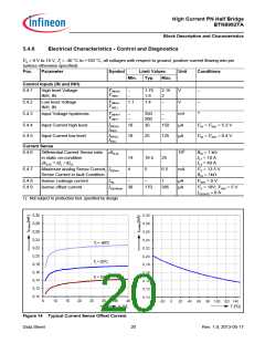
Current Sense / Status Flag IS
IS(offset) = Current sense - Offset (for
0 = Logic LOW
OFF = switched off
I
conditions see table: Current
Sense)
1 = Logic HIGH
X = 0 or 1
ON = switched on
CS = Current sense - high side (for
conditions see table: Current
Sense)
1 = Logic HIGH (error)
Data Sheet
19
Rev. 1.0, 2013-05-17

 INFINEON [ Infineon ]