IC80C51
IC80C31
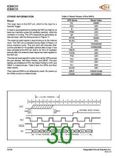
Table 9. Reset Values of the SFR's
OTHER INFORMATION
Reset
SFR Name
PC
Reset Value
0000H
00H
The reset input is the RST pin, which is the input to a
Schmitt Trigger.
ACC
B
00H
A reset is accomplished by holding the RST pin high for at
least two machine cycles (24 oscillator periods), while the
oscillator is running. The CPU responds by generating an
internal reset, with the timing shown in Figure 17.
PSW
SP
00H
07H
DPTR
P0-P3
IP
0000H
FFH
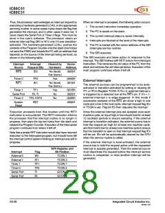
The external reset signal is asynchronous to the internal
clock. The RST pin is sampled during State 5 Phase 2 of
every machine cycle. The port pins will maintain their
current activities for 19 oscillator periods after a logic 1 has
been sampled at the RST pin; that is, for 19 to 31 oscillator
periods after the external reset signal has been applied to
the RST pin.
XX000000B
0X000000B
00H
IE
TMOD
TCON
TH0
00H
00H
The internal reset algorithm writes 0s to all the SFRs except
the port latches, the Stack Pointer, and SBUF. The port
latches are initialized to FFH, the Stack Pointer to 07H, and
SBUF is indeterminate. Table 9 lists the SFRs and their
reset values.
TL0
00H
TH1
00H
TL1
00H
SCON
SBUF
PCON
00H
Indeterminate
0XXX0000B
Then internal RAM is not affected by reset. On power-up
the RAM content is indeterminate.
12 OSC. PERIODS
S5 S6 S1 S2 S3 S4 S5 S6 S1 S2 S3 S4 S5 S6 S1 S2 S3 S4
RST
ALE
INTERNAL RESET SIGNAL
SAMPLE
RST
SAMPLE
RST
PSEN
P0
INST ADDR INST ADDR
11 OSC. PERIODS
INST
ADDR
INST ADDR INST
ADDR
19 OSC. PERIODS
Figure 17. Reset Timing
S3-30
Integrated Circuit Solution Inc.
MC001-0B

 ICSI [ INTEGRATED CIRCUIT SOLUTION INC ]