IC80C51
IC80C31
INTERRUPT SYSTEM
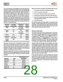
The IC80C51/31 provides six interrupt sources: two external
interrupts, two timer interrupts, and a serial port interrupt.
These are shown in Figure 15.
The Serial Port Interrupt is generated by the logical OR of
RI and TI. Neither of these flags is cleared by hardware
when the service routine is vectored to. In fact, the service
routine normally must determine whether RI or TI generated
the interrupt, and the bit must be cleared in software.
The External Interrupts INT0 and INT1 can each be either
level-activated or transition-activated, depending on bits
IT0 and IT1 in Register TCON. The flags that actually
generate these interrupts are the IE0 and IE1 bits in TCON.
When the service routine is vectored, hardware clears the
flag that generated an external interrupt only if the interrupt
was transition-activated. If the interrupt was level-activated,
then the external requesting source (rather than the on-
chip hardware) controls the request flag.
All of the bits that generate interrupts can be set or cleared
by software, with the same result as though they had been
set or cleared by hardware. That is, interrupts can be
generated and pending interrupts can be canceled in
software.
Each of these interrupt sources can be individually enabled
or disabled by setting or clearing a bit in Special Function
Register IE (interrupt enable) at address 0A8H. As well as
individual enable bits for each interrupt source, there is a
global enable/disable bit that is cleared to disable all
interrupts or set to turn on interrupts (see SFR IE).
The Timer 0 and Timer 1 Interrupts are generated by TF0
and TF1, which are set by a rollover in their respective
Timer/Counter registers (except for Timer 0 in Mode 3).
When a timer interrupt is generated, the on-chip hardware
clears the flag that generated it when the service routine is
vectored to.
POLLING
HARDWARE
HIGH PRIORITY
INTERRUPT
REQUEST
IE.0
IE.7
IP.0
TCON.1
EXTERNAL
INT RQST 0
INT0
EX0
IE.1
PX0
IP.1
IE0
TCON.5
TIMER/COUNTER 0
SOURCE
VECTOR
I.D.
ET0
IE.2
PT0
IP.2
TF0
TCON.3
EXTERNAL
INT RQST 1
IE1
INT1
EX1
IE.3
PX1
IP.3
TCON.7
TIMER/COUNTER 1
ET1
IE.4
PT1
IP.4
TF1
LOW PRIORITY
INTERRUPT
REQUEST
SCON.0
INTERNAL
RI
SERIAL
SCON.1
TI
PORT
PS
ES
EA
SOURCE
VECTOR
I.D.
Figure 15. Interrupt System
S3-26
Integrated Circuit Solution Inc.
MC001-0B

 ICSI [ INTEGRATED CIRCUIT SOLUTION INC ]