IC80C51
IC80C31
Table 10. Status of the External Pins During Idle and Power-down Modes.
Mode
Idle
Memory
Internal
External
Internal
External
ALE
PSEN
PORT 0
Data
PORT 1
Data
PORT 2
Data
PORT 3
Data
1
1
0
0
1
1
0
0
Idle
Float
Data
Address
Data
Data
Power-down
Power-down
Data
Data
Data
Float
Data
Data
Data
On-Chip Oscillators
The crystal specifications and capacitance values (C1 and
C2 in Figure 20) are not critical. 20 pF to 30 pF can be used
in these positions at a 12 MHz to 24 MHz frequency with
good quality crystals. (For ranges greater than 24 MHz refer
to Figure 21.) A ceramic resonator can be used in place of
the crystal in cost-sensitive applications. When a ceramic
resonator is used, C1 and C2 are normally selected to be of
somewhat higher values. The manufacturer of the ceramic
resonator should be consulted for recommendation on the
values of these capacitors.
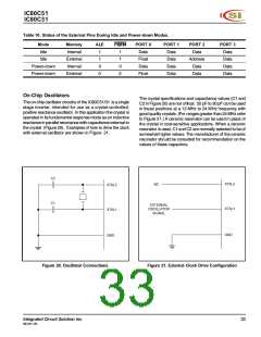
The on-chip oscillator circuitry of the IC80C51/31 is a single
stage inverter, intended for use as a crystal-controlled,
positive reactance oscillator. In this application the crystal is
operated in its fundamental response mode as an inductive
reactance in parallel resonance with capacitance external to
the crystal (Figure 20). Examples of how to drive the clock
with external oscillator are shown in Figure 21.
C2
XTAL2
XTAL1
NC
XTAL2
C1
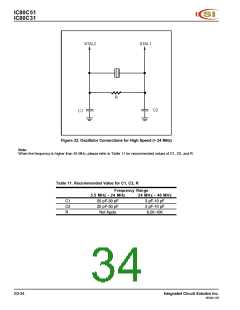
EXTERNAL
OSCILLATOR
SIGNAL
XTAL1
GND
GND
Figure 20. Oscillator Connections
Figure 21. External Clock Drive Configuration
Integrated Circuit Solution Inc.
MC001-0B
33

 ICSI [ INTEGRATED CIRCUIT SOLUTION INC ]