IC80C51
IC80C31
Power-Saving Modes of Operation
The IC80C51/31 has two power-reducing modes. Idle and
Power-down. The input through which backup power is
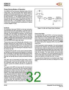
supplied during these operations is Vcc. Figure 19 shows
the internal circuitry which implements these features. In
the Idle mode (IDL = 1), the oscillator continues to run and
the Interrupt, Serial Port, and Timer blocks continue to be
clocked, but the clock signal is gated off to the CPU. In
Power-down (PD = 1), the oscillator is frozen. The Idle and
Power-down modes are activated by setting bits in Special
Function Register PCON.
XTAL 1
XTAL 2
OSC
PD
INTERRUPT,
SERIAL PORT,
TIMER BLOCKS
CLOCK
GEN
CPU
IDL
Idle Mode
Figure 19. Idle and Power-Down Hardware
An instruction that sets PCON.0 is the last instruction
executed before the Idle mode begins. In the Idle mode, the
internal clock signal is gated off to the CPU, but not to the
Interrupt, Timer, and Serial Port functions. The CPU status
is preserved in its entirety; the Stack Pointer, Program
Counter, Program Status Word, Accumulator, and all other
registers maintain their data during Idle. The port pins hold
the logical states they had at the time Idle was activated.
ALE and PSEN hold at logic high levels.
Power-down Mode
An instruction that sets PCON.1 is the last instruction
executed before Power-down mode begins. In the Power-
down mode, the on-chip oscillator stops. With the clock
frozen, all functions are stopped, but the on-chip RAM and
Special function Registers are held. The port pins output
the values held by their respective SFRs. ALE and PSEN
output lows.
There are two ways to terminate the Idle. Activation of any
enabled interrupt will cause PCON.0 to be cleared by
hardware, terminating the Idle mode. The interrupt will be
serviced, and following RETI the next instruction to be
executed will be the one following the instruction that put
the device into Idle.
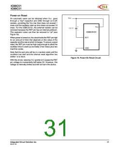
In the Power-down mode of operation, Vcc can be reduced
to as low as 2V. However, Vcc must not be reduced before
the Power-down mode is invoked, and Vcc must be restored
to its normal operating level before the Power-down mode
is terminated. The reset that terminates Power-down also
frees the oscillator. The reset should not be activated
before Vcc is restored to its normal operating level and
must be held active long enough to allow the oscillator to
restart and stabilize (normally less than 10 msec).
The flag bits GF0 and GF1 can be used to indicate whether
an interrupt occurred during normal operation or during an
Idle. For example, an instruction that activates Idle can also
set one or both flag bits. When Idle is terminated by an
interrupt, the interrupt service routine can examine the flag
bits.
The only exit from Power-down is a hardware reset. Reset
redefines all the SFRs but does not change the on-chip
RAM.
The other way of terminating the Idle mode is with a
hardware reset. Since the clock oscillator is still running,
the hardware reset must be held active for only two
machine cycles (24 oscillator periods) to complete the
reset.
The signal at the RST pin clears the IDL bit directly and
asynchronously. At this time, the CPU resumes program
execution from where it left off; that is, at the instruction
following the one that invoked the Idle Mode. As shown in
Figure 17, two or three machine cycles of program execution
may take place before the internal reset algorithm takes
control. On-chip hardware inhibits access to the internal
RAM during his time, but access to the port pins is not
inhibited. To eliminate the possibility of unexpected outputs
at the port pins, the instruction following the one that
invokes Idle should not write to a port pin or to external data
RAM.
S3-32
Integrated Circuit Solution Inc.
MC001-0B

 ICSI [ INTEGRATED CIRCUIT SOLUTION INC ]