IC80C51
IC80C31
Response Time
Single-Step Operation
The INT0 and INT1 levels are inverted and latched into the
interrupt flags IE0 and IE1 at S5P2 of every machine cycle.
Similarly, the Timer 2 flag EXF2 and the Serial Port flags RI
and TI are set at S5P2. The values are not actually polled
by the circuitry until the next machine cycle.
The IC80C51/31 interrupt structure allows single-step
execution with very little software overhead. As previously
noted, an interrupt request will not be serviced while an
interrupt of equal priority level is still in progress, nor will it
be serviced after RETI until at least one other instruction
has been executed. Thus, once an interrupt routine has
been entered, it cannot be re-entered until at least one
instruction of the interrupted program is executed. One
way to use this feature for single-step operation is to
program one of the external interrupts (for example, INT0)
to be level-activated. The service routine for the interrupt
will terminate with the following code:
The Timer 0 and Timer 1 flags, TF0 and TF1, are set at
S5P2 of the cycle in which the timers overflow. The values
are then polled by the circuitry in the next cycle. However,
the Timer 2 flag TF2 is set at S2P2 and is polled in the same
cycle in which the timer overflows.
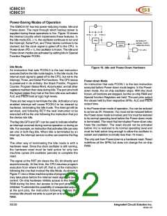
If a request is active and conditions are right for it to be
acknowledged, a hardware subroutine call to the requested
service routine will be the next instruction executed. The
call itself takes two cycles. Thus, a minimum of three
complete machine cycles elapsed between activation of an
external interrupt request and the beginning of execution of
the first instruction of the service routine. Figure 19 shows
response timings.
JNB
JB
P3.2,$
P3.2,$
;Wait Here Till INT0 Goes High
;Now Wait Here Till it Goes Low
RETI
;Go Back and Execute One
Instruction
A longer response time results if the request is blocked by
one of the three previously listed conditions. If an interrupt
of equal or higher priority level is already in progress, the
additional wait time depends on the nature of the other
interrupt's service routine. If the instruction in progress is
not in its final cycle, the additional wait time cannot be more
than three cycles, since the longest instructions (MUL and
DIV) are only four cycles long. If the instruction in progress
is RETI or an access to IE or IP, the additional wait time
cannot be more than five cycles (a maximum of one more
cycle to complete the instruction in progress, plus four
cycles to complete the next instruction if the instruction is
MUL or DIV).
If the INT0 pin, which is also the P3.2 pin, is held normally
low, the CPU will go right into the External Interrupt 0
routine and stay there until INT0 is pulsed (from low-to-
high-to-low). Then it will execute RETI, go back to the task
program, execute one instruction, and immediately re-
enter the External Interrupt 0 routine to await the next
pulsing of P3.2. One step of the task program is executed
each time P3.2 is pulsed.
Thus, in a single-interrupt system, the response time is
always more than three cycles and less than nine cycles.
Integrated Circuit Solution Inc.
MC001-0B
29

 ICSI [ INTEGRATED CIRCUIT SOLUTION INC ]