IC80C51
IC80C31
Priority Level Structure
Each interrupt source can also be individually programmed
to one of two priority levels by setting or clearing a bit in
Special Function Register IP (interrupt priority) at address
0B8H. IP is cleared after a system reset to place all
interrupts at the lower priority level by default. A low-priority
interrupt can be interrupted by a high-priority interrupt but
not by another low-priority interrupt. A high-priority interrupt
can not be interrupted by any other interrupt source.
LCALL to the appropriate service routine, provided this
hardware generated LCALL is not blocked by any of the
following conditions:
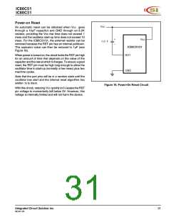
1. An interrupt of equal or higher priority level is already
in progress.
2. The current (polling) cycle is not the final cycle in the
execution of the instruction in progress.
If two requests of different priority levels are received
simultaneously, the request of higher priority level is
serviced. If requests of the same priority level are received
simultaneously, an internal polling sequence determines
which request is serviced. Thus, within each priority level
there is a second priority structure determined by the
polling sequence, as follows:
3. The instruction in progress is RETI or any write to the
IE or IP registers.
Any of these three conditions will block the generation of
the LCALL to the interrupt service routine. Condition 2
ensures that the instruction in progress will be completed
before vectoring to any service routine. Condition 3 ensures
that if the instruction in progress is RETI or any access to
IE or IP, then at least one more instruction will be executed
before any interrupt is vectored to.
Source
IE0
Priority Within Level
1.
2.
3.
4.
5.
(Highest)
The polling cycle is repeated with each machine cycle, and
the values polled are the values that were present at S5P2
of the previous machine cycle. If an active interrupt flag is
not being serviced because of one of the above conditions
and is not still active when the blocking condition is removed,
the denied interrupt will not be serviced. In other words, the
fact that the interrupt flag was once active but not serviced
is not remembered. Every polling cycle is new. The polling
cycle/LCALL sequence is illustrated in Figure 16.
TF0
IE1
TF1
R1 + T1
(Lowest)
Note that the "priority within level" structure is only used to
resolve simultaneous requests of the same priority level.
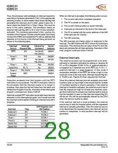
How Interrupts Are Handled
Note that if an interrupt of higher priority level goes active
prior to S5P2 of the machine cycle labeled C3 in Figure 16,
then in accordance with the above rules it will be serviced
during C5 and C6, without any instruction of the lower
priority routine having been executed.
The interrupt flags are sampled at S5P2 of every machine
cycle. The samples are polled during the following machine
cycle (the Timer 2 interrupt cycle is different, as described
in the Response Timer Section). If one of the flags was in
a set condition at S5P2 of the preceding cycle, the polling
cycle will find it and the interrupt system will generate an
C1
C2
C3
C4
C5
S5P2
S6
E
INTERRUPTS
ARE POLLED
LONG CALL TO
INTERRUPT
VECTOR ADDRESS
INTERRUPT
ROUTINE
INTERRUPT
LATCHED
INTERRUPT
GOES ACTIVE
Figure 16. Interrupt Response Timing Diagram
Integrated Circuit Solution Inc.
MC001-0B
27

 ICSI [ INTEGRATED CIRCUIT SOLUTION INC ]