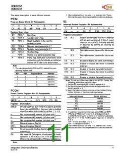
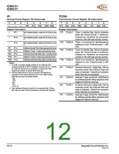
IC80C51
IC80C31
Mode 1:
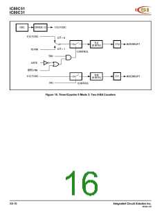
Mode 3:
Mode 1 is the same as Mode 0, except that the Timer
register is run with all 16 bits. The clock is applied to the
combined high and low timer registers (TL1/TH1). As
clock pulses are received, the timer counts up: 0000H,
0001H, 0002H, etc. An overflow occurs on the FFFFH-to-
0000H overflow flag. The timer continues to count. The
overflow flag is the TF1 bit in TCON that is read or written
by software (see Figure 9).
Timer 1 in Mode 3 simply holds its count. The effect is the
same as setting TR1 = 0. Timer 0 in Mode 3 establishes
TL0 and TH0 as two separate counters. The logic for Mode
3 on Timer 0 is shown in Figure 11. TL0 uses the Timer 0
control bits: C/T, GATE, TR0, INT0, and TF0. TH0 is
locked into a timer function (counting machine cycles) and
over the use of TR1 and TF1 from Timer 1. Thus, TH0 now
controls the Timer 1 interrupt.
Mode 3 is for applications requiring an extra 8-bit timer or
counter. With Timer 0 in Mode 3, the IC80C51 can appear
to have three Timer/Counters. When Timer 0 is in Mode 3,
Timer 1 can be turned on and off by switching it out of and
into its own Mode 3. In this case, Timer 1 can still be used
by the serial port as a baud rate generator or in any
application not requiring an interrupt.
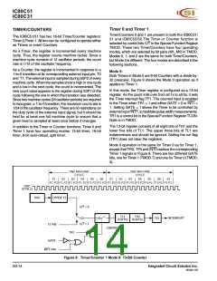
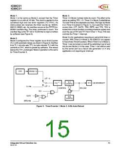
Mode 2:
Mode 2 configures the Timer register as an 8-bit Counter
(TL1) with automatic reload, as shown in Figure 9. Overflow
from TL1 not only sets TF1, but also reloads TL1 with the
contents of TH1, which is preset by software. The reload
leaves the TH1 unchanged. Mode 2 operation is the same
for Timer/Counter 0.
OSC
DIVIDE 12
C/T = 0
C/T = 1
TL1
(8 BITS)
INTERRUPT
TF1
T1 PIN
RELOAD
CONTROL
TR1
GATE
TH1
(8 BITS)
INT0 PIN
Figure 9. Timer/Counter 1 Mode 2: 8-Bit Auto-Reload
Integrated Circuit Solution Inc.
MC001-0B
15

 ICSI [ INTEGRATED CIRCUIT SOLUTION INC ]