IC80C51
IC80C31
SERIAL INTERFACE
The Serial port is full duplex, which means it can transmit
and receive simultaneously. It is also receive-buffered,
which means it can begin receiving a second byte before
a previously received byte has been read from the receive
register. (However, if the first byte still has not been read
when reception of the second byte is complete, one of the
bytes will be lost.) The serial port receive and transmit
registers are both accessed at Special Function Register
SBUF. Writing to SBUF loads the transmit register, and
reading SBUF accesses a physically separate receive
register.
Multiprocessor Communications
Modes 2 and 3 have a special provision for multiprocessor
communications. In these modes, nine data bits are
received, followed by a stop bit. The ninth bit goes into RB8;
then comes a stop bit. The port can be programmed such
that when the stop bit is received, the serial port interrupt
is activated only if RB8 = 1. This feature is enabled by
setting bit SM2 in SCON.
The following example shows how to use the serial interrupt
for multiprocessor communications. When the master
processor must transmit a block of data to one of several
slaves, it first sends out an address byte that identifies the
target slave. An address byte differs from a data byte in that
the ninth bit is 1 in an address byte and 0 in a data byte. With
SM2 = 1, no slave is interrupted by a data byte. An address
byte, however, interrupts all slaves, so that each slave can
examine the received byte and see if it is being addressed.
The addressed slave clears its SM2 bit and prepares to
receive the data bytes that follows. The slaves that are not
addressed set their SM2 bits and ignore the data bytes.
The serial port can operate in the following four modes:
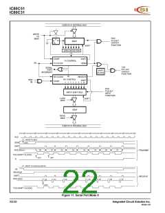
Mode 0:
Serial data enters and exits through RXD. TXD outputs the
shift clock. Eight data bits are transmitted/received, with
the LSB first. The baud rate is fixed at 1/12 the oscillator
frequency (see Figure 11).
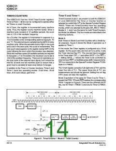
Mode 1:
Ten bits are transmitted (through TXD) or received (through
RXD): a start bit (0), eight data bits (LSB first), and a stop
bit (1). On receive, the stop bit goes into RB8 in Special
Function Register SCON. The baud rate is variable (see
Figure 12).
SM2 has no effect in Mode 0 but can be used to check the
validity of the stop bit in Mode 1. In a Mode 1 reception, if
SM2 = 1, the receive interrupt is not activated unless a valid
stop bit is received.
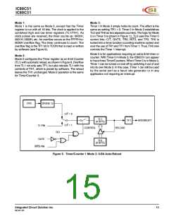
Mode 2:
Eleven bits are transmitted (through TXD) or received
(through RXD): a start bit (0), eight data bits (LSB first), a
programmable ninth data bit, and a stop bit (1). On transmit,
the ninth data bit (TB8 in SCON) can be assigned the value
of 0 or 1. Or, for example, the parity bit (P, in the PSW) can
be moved into TB8. On receive, the ninth data bit goes into
RB8 in Special Function Register SCON, while the stop bit
is ignored. The baud rate is programmable to either 1/32 or
1/64 the oscillator frequency (see Figure 13).
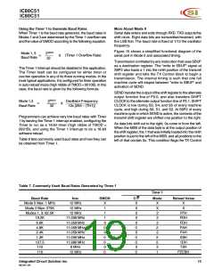
Baud Rates
The baud rate in Mode 0 is fixed as shown in the following
equation.
Oscillator Frequency
Mode 0 Baud Rate =
12
The baud rate in Mode 2 depends on the value of the SMOD
bit in Special Function Register PCON. If SMOD = 0 (the
value on reset), the baud rate is 1/64 of the oscillator
frequency. If SMOD = 1, the baud rate is 1/32 of the
oscillator frequency, as shown in the following equation.
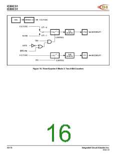
Mode 3:
Eleven bits are transmitted (through TXD) or received
(through RXD): a start bit (0), eight data bits (LSB first), a
programmable ninth data bit, and a stop bit (1). In fact,
Mode 3 is the same as Mode 2 in all respects except the
baud rate, which is variable in Mode 3 (see Figure 14).
2SMOD
64
Mode 2 Baud Rate =
x (Oscillator Frequency)
In all four modes, transmission is initiated by any instruction
that uses SBUF as a destination register. Reception is
initiated in Mode 0 by the condition RI = 0 and REN = 1.
Reception is initiated in the other modes by the incoming
start bit if REN = 1.
In the IC80C51/31, the Timer 1 overflow rate da termines
th e baud rates in Modes 1 and 3.
S3-18
Integrated Circuit Solution Inc.
MC001-0B

 ICSI [ INTEGRATED CIRCUIT SOLUTION INC ]