IC80C51
IC80C31
Timer 0 and Timer 1
TIMER/COUNTERS
Timer/Counters 0 and 1 are present in both the IC80C51/
31 and IC80C52/32.The Timer or Counter function is
selected by control bits C/T in the Special Function Regiser
TMOD. These two Timer/Counters have four operating
modes, which are selected by bit pairs (M1, M0) in TMOD.
Modes 0, 1, and 2 are the same for both Timer/Counters,
but Mode 3 is different. The four modes are described in the
following sections.
The IC80C51/31 has two 16-bit Timer/Counter registers:
Timer 0,Timer 1. All two can be configured to operate either
as Timers or event Counters.
As a Timer, the register is incremented every machine
cycle. Thus, the register counts machine cycles. Since a
machine cycle consists of 12 oscillator periods, the count
rate is 1/12 of the oscillator frequency.
As a Counter, the register is incremented in response to a
1-to-0 transition at its corresponding external input pin, T0
and T1. The external input is sampled during S5P2 of every
machine cycle. When the samples show a high in one cycle
and a low in the next cycle, the count is incremented. The
new count value appears in the register during S3P1 of the
cycle following the one in which the transition was detected.
Since two machine cycles (24 oscillator periods) are required
to recognize a 1-to-0 transition, the maximum count rate is
1/24 of the oscillator frequency. There are no restrictions on
the duty cycle of the external input signal, but it should be
held for at least one full machine cycle to ensure that a
given level is sampled at least once before it changes.
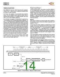
Mode 0:
Both Timers in Mode 0 are 8-bit Counters with a divide-by-
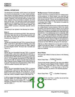
32 prescaler. Figure 8 shows the Mode 0 operation as it
applies to Timer 1.
In this mode, the Timer register is configured as a 13-bit
register. As the count rolls over from all 1s to all 0s, it sets
the Timer interrupt flag TF1. The counted input is enabled
to the Timer when TR1 = 1 and either GATE = 0 or INT1 =
1. Setting GATE = 1 allows the Timer to be controlled by
external input INT1, to facilitate pulse width measurements.
TR1 is a control bit in the Special Function Register TCON.
Gate is in TMOD.
The 13-bit register consists of all eight bits of TH1 and the
lower five bits of TL1. The upper three bits of TL1 are
indeterminate and should be ignored. Setting the run flag
(TR1) does not clear the registers.
In addition to the Timer or Counter functions, Timer 0 and
Timer 1 have four operating modes: 13-bit timer, 16-bit
timer, 8-bit auto-reload, split timer.
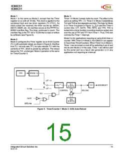
Mode 0 operation is the same for Timer 0 as for Timer 1,
except that TR0, TF0 and INT0 replace the corresponding
Timer 1 signals in Figure 8. There are two different GATE
bits, one for Timer 1 (TMOD.7) and one for Timer 0 (TMOD.
3).
ONE MACHINE
CYCLE
ONE MACHINE
CYCLE
S1
S2
S3
S4
S5
S6
S1
S2
S3
S4
S5
S6
S1
P1 P2 P1 P2 P1 P2 P1 P2 P1 P2 P1 P2 P1 P2 P1 P2 P1 P2 P1 P2 P1
P1P2 P1 P2
P2
OSC
(XTAL2)
OSC
DIVIDE 12
C/T = 0
TL1
TH1
INTERRUPT
TF1
(5 BITS) (8 BITS)
C/T = 1
T1 PIN
CONTROL
TR1
GATE
INT1 PIN
Figure 8. Timer/Counter 1 Mode 0: 13-Bit Counter
S3-14
Integrated Circuit Solution Inc.
MC001-0B

 ICSI [ INTEGRATED CIRCUIT SOLUTION INC ]