IC80C51
IC80C31
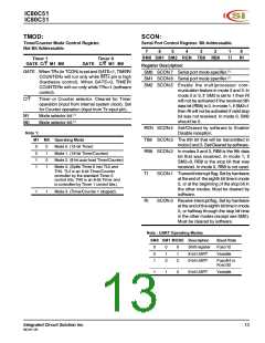
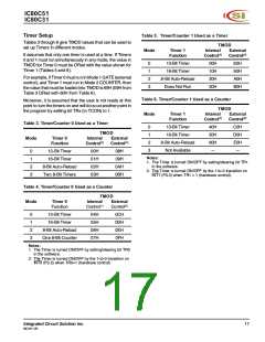
TMOD:
Timer/Counter Mode Control Register.
Not Bit Addressable.
SCON:
Serial Port Control Register. Bit Addressable.
7
6
5
4
3
2
1
0
SM0 SM1 SM2 REN TB8 RB8
TI
RI
Timer 1
GATE C/T M1 M0
Timer 0
GATE C/T M1 M0
Register Description:
SM0 SCON.7 Serial port mode specifier.(1)
SM1 SCON.6 Serial port mode specifier.(1)
GATE When TRx (in TCON) is set and GATE=1, TIMER/
COUNTERx will run only while INTx pin is high
(hardware control). When GATE=0, TIMER/
COUNTERx will run only while TRx=1 (software
control).
SM2 SCON.5 Enable the multiprocessor com-
munication feature in mode 2 and 3. In
mode 2 or 3, if SM2 is set to 1 then RI
will not be activated if the received 9th
data bit (RB8) is 0. In mode 1, if SM2=1
then RI will not be activated if valid stop
bit was not received. In mode 0, SM2
should be 0.
C/T
Timer or Counter selector. Cleared for Timer
operation (input from internal system clock). Set
for Counter operation (input from Tx input pin).
M1
M0
Mode selector bit.(1)
Mode selector bit.(1)
REN SCON.4 Set/Cleared by software to Enable/
Disable reception.
Note 1:
M1 M0 Operating Mode
TB8 SCON.3 The 9th bit that will be transmitted in
mode 2 and 3. Set/Cleared by software.
0
0
1
1
0
1
0
1
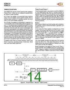
Mode 0. (13-bit Timer)
RB8 SCON.2 In modes 2 and 3, RB8 is the 9th data
bit that was received. In mode 1, if
Mode 1. (16-bit Timer/Counter)
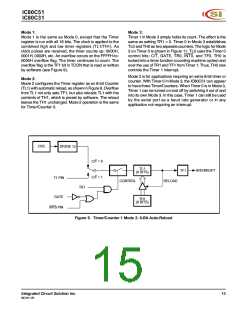
Mode 2. (8-bit auto-load Timer/Counter)
SM2=0, RB8 is the stop bit that was
received. In mode 0, RB8 is not used.
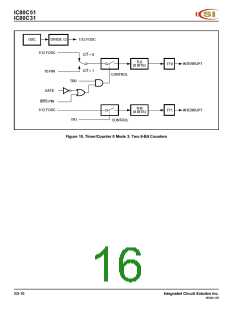
Mode 3. (Splits Timer 0 into TL0 and
TH0. TL0 is an 8-bit Timer/Counter
controller by the standard Timer 0
control bits. TH0 is an 8-bit Timer and
is controlled by Timer 1 control bits.)
TI
SCON.1 Transmit interrupt flag. Set by hardware
at the end of the eighth bit time in mode
0, or at the beginning of the stop bit in
the other modes. Must be cleared by
software.
1
1
Mode 3. (Timer/Counter 1 stopped).
RI
SCON.0 Receive interrupt flag. Set by hardware
at the end of the eighth bit time in mode
0, or halfway through the stop bit time
in the other modes (except see SM2).
Must be cleared by software.
Note : UART Operating Modes
SM0 SM1 MODE Description
Baud Rate
Fosc/12
0
0
1
0
1
0
0
1
2
Shift register
8-bit UART
9-bit UART
Variable
Fosc/64 or
Fosc/32
1
1
3
9-bit UART
Variable
Integrated Circuit Solution Inc.
MC001-0B
13

 ICSI [ INTEGRATED CIRCUIT SOLUTION INC ]