IC80C51
IC80C31
Timer Setup
Table 5. Timer/Counter 1 Used as a Timer
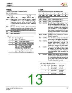
TMOD
Tables 3 through 6 give TMOD values that can be used to
set up Timers in different modes.
Mode
Timer 1
Function
Internal
Control(1)
External
Control(2)
It assumes that only one timer is used at a time. If Timers
0 and 1 must run simultaneously in any mode, the value in
TMOD for Timer 0 must be ORed with the value shown for
Timer 1 (Tables 5 and 6).
0
1
2
3
13-Bit Timer
16-Bit Timer
00H
80H
90H
A0H
B0H
10H
For example, if Timer 0 must run in Mode 1 GATE (external
control), and Timer 1 must run in Mode 2 COUNTER, then
the value that must be loaded into TMOD is 69H (09H from
Table 3 ORed with 60H from Table 6).
8-Bit Auto-Reload
Does Not Run
20H
30H
Table 6. Timer/Counter 1 Used as a Counter
TMOD
Moreover, it is assumed that the user is not ready at this
point to turn the timers on and will do so at another point in
the program by setting bit TRx (in TCON) to 1.
Mode
Timer 1
Function
Internal
Control(1)
External
Control(2)
Table 3. Timer/Counter 0 Used as a Timer
TMOD
0
1
2
3
13-Bit Timer
16-Bit Timer
40H
50H
60H
—
C0H
D0H
E0H
—
Mode
Timer 0
Function
Internal
Control(1)
External
Control(2)
8-Bit Auto-Reload
Not Available
0
1
2
3
13-Bit Timer
16-Bit Timer
00H
01H
02H
03H
08H
09H
0AH
0BH
Notes:
1. The Timer is turned ON/OFF by setting/clearing bit TR1
in the software.
2. The Timer is turned ON/OFF by the 1-to-0 transition on
INT1 (P3.3) when TR1 = 1 (hardware control).
8-Bit Auto-Reload
Two 8-Bit Timers
Table 4. Timer/Counter 0 Used as a Counter
TMOD
Mode
Timer 0
Function
Internal
Control(1)
External
Control(2)
0
1
2
3
13-Bit Timer
16-Bit Timer
04H
05H
06H
07H
0CH
0DH
0EH
0FH
8-Bit Auto-Reload
One 8-Bit Counter
Notes:
1. The Timer is turned ON/OFF by setting/clearing bit TR0
in the software.
2. The Timer is turned ON/OFF by the 1-to-0 transition on
INT0 (P3.2) when TR0=1 (hardware control)
Integrated Circuit Solution Inc.
MC001-0B
17

 ICSI [ INTEGRATED CIRCUIT SOLUTION INC ]