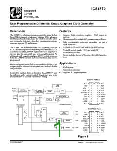
ICS1572
ICS1572-101 The ICS1572-101 supports phase detector
disable via a special control mode. When the
PDRSTEN (phase detector reset enable) bit is
set, a high level on AD3 will disable PLL
locking.
Reference Oscillator and Crystal
Selection
The ICS1572 has circuitry on-board to implement a Pierce
oscillator with the addition of only one external component, a
quartz crystal. Pierce oscillators operate the crystal in anti-
(also called parallel-) resonant mode. See the AC Charac-
teristics for the effective capacitive loading to specify when
ordering crystals.
ICS1572-301 The ICS1572-301 supports phase detector
disable via the BLANK pin. When the
PDRSTEN bit is set, a high level on the
BLANK input will disable PLL locking.
Series-resonant crystals may also be used with the ICS1572.
Be aware that the oscillation frequency will be slightly higher
than the frequency that is stamped on the can (typically 0.025-
0.05%).
External Feedback Operation
The ICS1572-301 option also supports the inclusion of an
external counter as the feedback divider of the PLL. This mode
is useful in graphic systems that must be “genlocked” to
external video sources.
As the entire operation of the phase-locked loop depends on
having a stable reference frequency, we recommend that the
crystal bemounted as closely as possible to the package. Avoid
routing digital signals or the ICS1572 outputs underneath or
near these traces. It is also desirable to ground the crystal can
to the ground plane, if possible.
When the EXTFBEN bit is set to logic 1, the phase-frequency
detector will use the EXTFBK pin as its feedback input. The
loop phase will be locked to the rising edges of the signal
applied to the EXTFBK input.
If an external reference frequency source is to be used with the
ICS1572, it is important that it be jitter-free. The rising and
falling edges of that signal should be fast and free of noise for
best results.
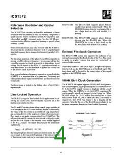
VRAM Shift Clock Generation
The ICS1572-301 option supports VRAM shift clock genera-
tionandinterruption. By programming theN2countertodivide
by 1, the LD/N2 output becomes a duplicate of the LOAD
output. When the SCEN bit is set, the LD/N2 output may be
synchronously started and stopped via the blank pin. When
BLANK is high, the LD/N2 will be free-running and in phase
with LOAD. When BLANK is taken low, the LD/N2 output is
stopped at a low level. See Figure 5 for a diagram of the
sequence. Note that this use of the BLANK pin precludes its use
for phase comparator disable (see Line-Locked Operation).
The loop phase is locked to the falling edges of the XTAL1
input signals.
Line-Locked Operation
The ICS1572 supports line-locked clock applications by al-
lowing the LOAD (N1) and N2 divider chains to act as the
feedback divider for the PLL.
The N1 and N2 divider chains allow a much larger modulus to
beachievedthanthePLL’s ownfeedbackdivider.Additionally,
the output of the N2 counter is accessible off-chip for perform-
ing horizontal reset of the graphics system, where necessary.
This mode is set under register control (ALTLOOP bit). The
reference divider (R counter) is set to divide by 1 in this mode,
and the HSYNC signal of the external video will be supplied
to the XTAL1 input. The output frequency of the synthesizer
will then be:
VRAM Shift Clock Control
BLANK
LOAD
LD/N2
. .
(CLK) : = F (XTAL1) N1 N2.
F
By using the phase-detector hardware disable mode, the PLL
can be made to free-run at the beginning of the vertical interval
of the external video, and can be reactivated at its completion.
Figure 5
4

 ICSI [ INTEGRATED CIRCUIT SOLUTION INC ]