ICS1531 Data Sheet - Preliminary
Chapter 6 Register Set
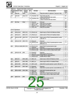
Table 6-3. Input Control Register (Continued)
Bit
Bit Name
Bit Definition
Ac- Spec. Re-
cess Func.
set
00:0
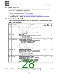
PD_En
Phase/(Frequency) Detector Enable.
R/W
–
1
This bit is used to enable the Phase/Frequency Detector.
Typically, the signal for this bit is from the source of the VSYNC
signal to a display.
• 0 = The Phase/Frequency Detector is disabled temporarily
and ‘coasts’ (that is, it continues to be disabled) as long as
the signal from the PDEN pin is in an active state. (See
Reg 00:1).
• 1 = The Phase/Frequency Detector is enabled regardless
of the PDEN pin state. (This state overrides Reg 00:1.)
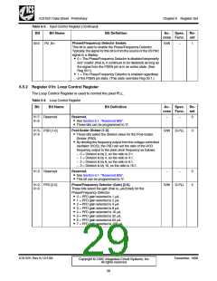
6.5.2 Register 01h: Loop Control Register
The Loop Control Register is used to control the pixel PLL.
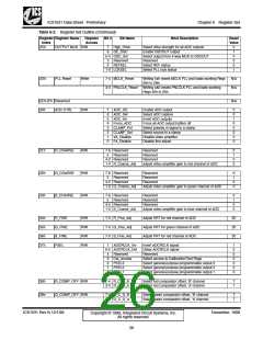
Table 6-4. Loop Control Register
Bit
Bit Name
Bit Definition
Ac- Spec. Re-
cess Func.
set
R•esSeerveeSde.ction 6.1, “Reserved Bits”.
• These bits can be programmed to ‘0’.
01:7- Reserved
01:6
–
–
0
P•osTt-hSecsaelebritsDsiveildeectr t[h1e-0d]i.vision value for the Post-Scaler
01:5- PSD [1-0]
01:4
R/W
D-PLL
0
Divider (PSD).
• By dividing the frequency output from the voltage-controlled
oscillator (VCO), the PSD can set the ratio of the VCO
frequency output to the pixel clock frequency as follows.
– 0 = Division is by 2, so the ratio is 2:1.
– 1 = Division is by 4, so the ratio is 4:1.
– 2 = Division is by 8, so the ratio is 8:1.
– 3 = Division is by 16, so the ratio is 16:1.
R•esSeerveeSde.ction 6.1, “Reserved Bits”.
• This bit can be programmed to ‘0’.
Phase/Frequency Detector (Gain) [2-0].
These bits select the gain (that is, µA/2πrad) for the
01:3 Reserved
–
–
0
0
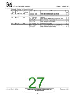
01:2- PFD [2-0]
01:0
R/W
D-PLL
P•ha0se=/FPrFeDqugeanicnysDeleetcetcetdori.s 1 µA.
• 1 = PFD gain selected is 2 µA.
• 2 = PFD gain selected is 4 µA.
• 3 = PFD gain selected is 8 µA.
• 4 = PFD gain selected is 16 µA.
• 5 = PFD gain selected is 32 µA.
• 6 = PFD gain selected is 64 µA.
• 7 = PFD gain selected is 128 µA.
ICS1531 Rev N 12/1/99
December, 1999
Copyright © 1999, Integrated Circuit Systems, Inc.
All rights reserved.
29

 ICSI [ INTEGRATED CIRCUIT SOLUTION INC ]