iC-MR 13-BIT S&H SIN/COS
INTERPOLATOR WITH CONTROLLER INTERFACES
Rev A1, Page 38/44
ABSOLUTE DATA INTERFACE (ADI)
DL_ADI
Code
0x00
0x01
...
Addr. 0x1A; bit 7...3
R/W
Through the absolute data interface the cycle counter
can be preloaded to a required value. The absolute
data interface is a BiSS master and operates on either
BiSS C or SSI protocol. Pin AMAO outputs the master
clock, with slave data read in at pin ASLI.
Function
0 bit MT / 0 bit ST
0 bit MT / 1 bit ST
...
0x0C
...
0 bit MT / 12 bit ST
...
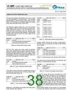
The following registers define the use of the absolute
data interface. Bit STP_ADI controls the readin of ab-
solute data during startup. If set, and after the EEP-
ROM has been successfully read out, absolute data
is read in by the absolute data interface. Alternatively,
absolute data can be read in at a later stage by the
command register.
0x17
0x18
0x19
0x1A
0x1B
0x1C
...
0 bit MT / 23 bit ST
0 bit MT / 24 bit ST
8 bit MT / 24 bit ST
12 bit MT / 24 bit ST
16 bit MT / 24 bit ST
24 bit MT / 24 bit ST
...
0x1F
24 bit MT / 24 bit ST
STP_ADI
Addr. 0x18; bit 3
Function
R/W
Table 72: Data length absolute data interface
Code
0
1
Do not read absolute data during start-up
Read absolute data during start-up
Register SYNC_ADI sets the number of synchroniza-
tion bits used to synchronize the data on the internal
cycle counter.
Table 69: Startup with absolute data
SYNC_ADI
Addr. 0x1A; bit 2...1
Function
R/W
Code
00
Bit CYC_ADI controls the cyclic readin of absolute
data. If set, absolute data is read in every 550 µs, pro-
vided the absolute data interface is not busy. Should
the absolute data interface be busy, the reading is suit-
ably delayed. If this bit is disabled, absolute data must
be read in through the command register.
Use 0 bit for synchronisation
Use 1 bit for synchronisation
Use 2 bit for synchronisation
Use 3 bit for synchronisation
01
10
11
Table 73: Synchronisation bits absolute data interface
CYC_ADI
Addr. 0x18; bit 2
Function
R/W
The transmission protocol used for the absolute data
interface is selected by bit SSI_ADI.
Code
0
1
Do not read absolut data cyclically
Read absolute data cyclically
SSI_ADI
Addr. 0x1A; bit 0
Function
R/W
Code
Table 70: Cyclic reading of absolute data
0
1
BiSS C protocol
SSI protocol
CHK_ADI is used to check the counted value versus a
cyclically read absolute value. If the two values differ,
error bit ERR_ABS will be set.
Table 74: Protocol of absolute data interface
In order to access the sensor connected up to the
absolute data interface through the serial interface in
BiSS C protocol, bit GET_ADI permits the interface
signals to be looped through to the absolute data in-
terface. To this end the master clock received at pin
MAI is output at pin AMAO and the data read at ASLI
is used internally in place of SLI. The sensor con-
nected up to the absolute data interface is then allocat-
ing slave ID 0 in BiSS C protocol, and iC-MR is taking
slave ID 1.
CHK_ADI
Addr. 0x27; bit 5
Funktion
R/W
Code
0
1
Do not check data cyclically
Check data cyclically versus ADI reading
Table 71: Cyclic check of absolute data
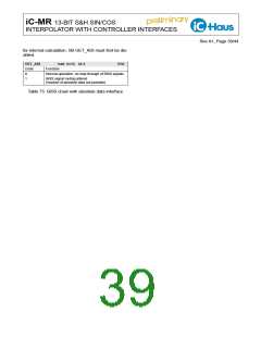
Register DL_ADI defines the length of the data read in When routing signals in this manner it is not possible
at the absolute data interface. to read in the absolute data of the connected sensor

 ICHAUS [ IC-HAUS GMBH ]