iC-MR 13-BIT S&H SIN/COS
INTERPOLATOR WITH CONTROLLER INTERFACES
Rev A1, Page 26/44
INTERPOLATOR AND CYCLE COUNTER
The configurable 37-bit cycle counter comparates the at 13-bit interpolation, the value ’10’ is accrued as the
sine and cosine signals and counts the signal cycles configuration for CODERES.
independent of requests for position data. The inter-
polator resolves one signal cycle of the calibrated sine
and cosine signals to 13 bits for each position data re-
quest and synchronizes this with the cycle counter in
order to ensure a consistent position data word at all
times.
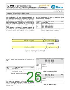
Using register CODERES it is possible to adapt the
bit length of the cycle counter to the output format. If,
for example, a total data length of 48 bits is required
CODERES
Addr. 0x1B; bit 1...0
R/W
Code
00
Counter depth
37 bit (24 bit MT, 13 bit ST)
36 bit (24 bit MT, 12 bit ST)
35 bit (24 bit MT, 11 bit ST)
34 bit (24 bit MT, 10 bit ST)
01
10
11
Table 37: Cycle counter resolution
36
3
12
0
0
0
0
Period Counter (36:3)
Interpolation (12:0)
CODERES
Period Counter (36:0)
Interpolation (12:0)
36
0
12
0
Figure 13: Adjusting the counter depth
STOFF
Addr. 0x1E; bit 7...0
Addr. 0x1D; bit 7...0
Addr. 0x1C; bit 7...0
Addr. 0x1B; bit 7...6
R/W
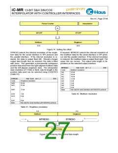
iC-MR’s output code direction can be inverted by bit
DIR.
Code
0x00
Function
Offset value
DIR
Code
0
Addr. 0x1B; bit 2
Code direction
R/W
0x3FFFFFF
Code direction not inverted
Code direction inverted
1
Table 39: Singleturn offset
Table 38: Inversion of code direction
MTOFF
Addr. 0x21; bit 7...0
Addr. 0x20; bit 7...0
Addr. 0x1F; bit 7...0
Function
R/W
Code
0x00
Offset value
An offset for singleturn (STOFF) and multiturn
(MTOFF) data can be defined to adapt the absolute
position data. These offsets are subtracted from the
existing data.
0xFFFFFF
Table 40: Multiturn offset

 ICHAUS [ IC-HAUS GMBH ]