APCPCWM_4828539:WP_0000001WP_0000001
1
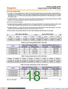
H27(U_S)4G8_6F2D
4 Gbit (512M x 8 bit) NAND Flash
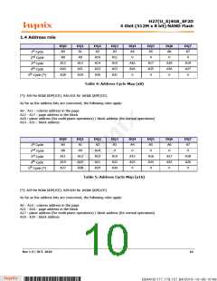
3. DEVICE OPERATION
3.1. Page Read
This operation is initiated by writing 00h and 30h to the command register along with five address cycles. Two types of
operations are available: random read, serial page read. The random read mode is enabled when the page address is
changed. The 2112 bytes (x8) or 1056 (x16) of data within the selected page are transferred to the data registers in
less than 25us(tR). The system controller may detect the completion of this data transfer (tR) by analyzing the output
of R/B pin. Once the data in a page is loaded into the data registers, they may be read out in 25ns (3V version) and
45nsec (1.8V version) cycle time by sequentially pulsing RE#. The repetitive high to low transitions of the RE# clock
make the device output the data starting from the selected column address up to the last column address.
The device may output random data in a page instead of the sequential data by writing random data output command.
The column address of next data, which is going to be out, may be changed to the address which follows random data
output command.
Random data output can be operated multiple times regardless of how many times it is done in a page.
After power up device is in read mode, so 00h command cycle is not necessary to start a read operation. Any operation
other than read or random data output causes device to exit read mode.
Check Figure 12, Figure 13, Figure 14 as references.
3.2 Data handling restirctions during program sequences
Applications which use the error detection code in copy back must respect some restrictions related to data handling
during program sequence.
The error dection code check is used during copy back program and multiplane copy back program operations to detect
single bit errors pccurred in the source page (for details about EDC)
Note: The restrictions described below are not valid if the application uses the copy back program or multiplane copy
back program without EDC check.
When data handling is performed, the page program, multiplane page program, page re-program, multiplane page re-
program, cache ptrgram and multiplane cache program operations, must respect the following restrictions:
1. Program operations must be performed on the whole page, or on the whple EDC unit at a time.
2. For each program operation, random data input can be executed only once for each EDC unit.
Copy back program or multiplane copy back program opeations must respect the following restrictions:
1. If rando, data input is applied in a given EDC unit, the data of the whole EDC unit must be inserted. In ohter words, the
EDC check is possible only if the whole EDC unit is modified during a copy back program sequence.
2. For each program operation, rando, data input can be executed only once for each EDC unit.
3.3 Page Program
A page program cycle consists of a serial data loading period in which up to 2112 bytes of data may be loaded into the
data register, followed by a non-volatile programming period where the loaded data is programmed into the appropriate
cell.
The serial data loading period begins by inputting the Serial Data Input command (80h), followed by the five cycle
address inputs and then serial data. The words other than those to be programmed do not need to be loaded. The
device supports random data input within a page. The column address of next data, which will be entered, may be
changed to the address which follows random data input command (85h). Random data input may be operated multi-
ple times regardless of how many times it is done in a page.
The Page Program confirm command (10h) initiates the programming process. The internal write state controller
automat-
Rev 1.4 / OCT. 2010
14
B34416/177.179.157.84/2010-10-08 10:08
*ba53f20d-240c*

 HYNIX [ HYNIX SEMICONDUCTOR ]